Electric-heating floor system and electric-heating floor

An electric heating floor and floor technology, which is applied in the field of building decoration, can solve the problems of high requirements for connecting power lines, potential safety hazards, and short contact distances

Inactive Publication Date: 2013-01-30
江苏德威木业有限公司
View PDF9 Cites 10 Cited by
  • Summary
  • Abstract
  • Description
  • Claims
  • Application Information

AI Technical Summary

Problems solved by technology

The disadvantage of this electric heating floor system is that the power supply method using plugs and sockets between adjacent floors is unreliable. This is because the thickness of the floor is usually not more than 1.2 cm. Special plugs and sockets, even if the distance between the plugs and sockets is very short, a little carelessness will cause poor contact, which will not only affect normal heating, but also cause safety hazards
The electric heating floors in this document are powered in parallel. Although the failure of one electrical connection will cause the failure of all floors or a row of floor electrical connectio

Method used


Image

  • Electric-heating floor system and electric-heating floor
  • Electric-heating floor system and electric-heating floor
  • Electric-heating floor system and electric-heating floor

Examples


Embodiment 1

[0116] (Example 1, electric heating floor)

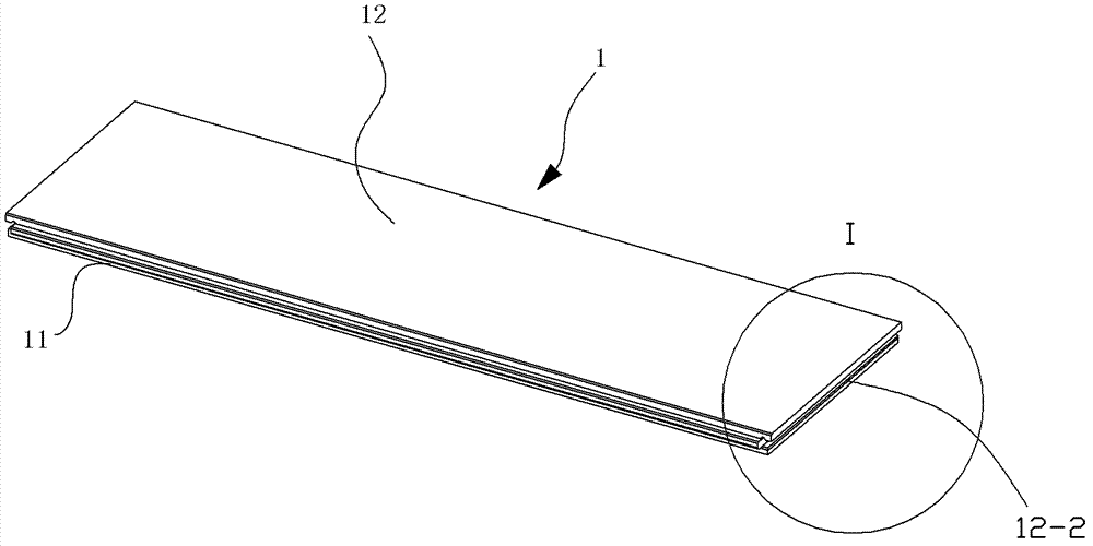
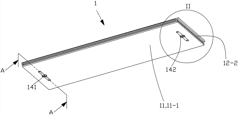
[0117] See Figure 1 to Figure 4 with Figure 7 , The electric heating floor 1 of this embodiment includes a bottom plate 11 , an upper plate 12 , a heating plate 13 and a plug assembly 14 .

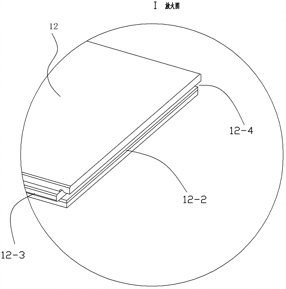
[0118] See figure 1 , image 3 with Figure 7 , the upper plate 12 is a homogeneous piece of wood, including a main body part 12-1 whose basic shape is a cuboid, a tenon part 12-3 located on the front side of the main part 12-1, and a tenon part located on the rear side of the main part 12-1. The insertion groove part 12-4 of the body part 12-1 and the fastening groove part 12-2 located on the left and right sides of the main body part 12-1. The insertion tenon part 12-3 is the position where the insertion grooves of the electric heating floors adjacent to the front side are connected and matched with each other during use, and the insertion groove part 12-4 is the insertion connection of the electric heating floors adjacent to the rear s...

Embodiment 2

[0129] (Example 2, electric heating floor system)

[0130] See Figure 11 with Figure 12 , when this embodiment describes the electric heating floor system, its front and rear, left and right, and up and down directions are the same as those described in Embodiment 1, that is, the Figure 11 The length direction of the mounting base 2 is the front-to-back direction, that is, Figure 11 The lower left in the middle is the front side, and the upper right is the rear side, that is, the Figure 12 The up, down, left, and right directions of are the described up, down, left, and right directions.

[0131] See Figure 27 , The electric heating floor system of this embodiment includes an electric heating floor, an installation base 2, a plug-in blocking member 31 and a power supply system. The power supply system includes a power supply line 600 and a keel line 400 . The electric heating floor adopts the electric heating floor 1 of Embodiment 1.

[0132] See Figure 11 , the...

Embodiment 3

[0158] (Embodiment 3, electric heating floor system)

[0159] See Figure 28 with Figure 29 , the rest of this embodiment is the same as that of Embodiment 2, the difference is that: the keel socket 4 also includes a wiring barrel 43, and the wiring barrel 43 and the copper sleeve 42 are an integral piece of the same material. When making this integral piece, a small piece The rectangular copper sheet 44 is provided with one or two bending grooves 44-2 (two in this embodiment) along the width direction, and a small section of copper sheet is reserved as the connection part 44-1. Then, 3 to 5 grooves (3 in this embodiment) are horizontally provided at equal intervals on the copper sheet located on the right side. Then the copper sheet is rolled into a cylindrical shape along the width direction, thereby forming the wiring barrel 43 on the left side of the connection part 44-1 and the copper sleeve 42 on the right side of the connection part 44-1, and three horizontally arran...


PUM

PropertyMeasurementUnit
Depthaaaaaaaaaa
Thicknessaaaaaaaaaa

Abstract

The invention discloses an electric-heating floor system. The electric-heating floor system is characterized by comprising electric-heating floors, mounting seats, inserting stoppers and a power supply system. The power supply system comprises power supply circuits and keel circuits. When the electric-heating floor system is mounted, firstly each mounting seat is laid on the ground horizontally from the length direction and from the backward to the forward, each process corresponding keel circuit is placed into a socket of the corresponding mounting seat, a first keel socket of each keel circuit is in waterproof inserting fit and electrically connected with a power socket of the corresponding power circuit, and finally the electric-heating floors are fixedly connected to the corresponding mounting seat through the inserting stoppers respectively, are in mutual waterproof inserting fit and electrically connected with the keel sockets of the corresponding keel circuits through socket components and operate in a series connection manner, all the electric-heating floors heat together for heating when a power is on, and operation of the other electric-heating floors is free of influence from damage of a certain electric-heating floor.

Description

technical field [0001] The invention relates to a product in the field of building decoration, in particular to an electric heating floor system and the electric heating floor. Background technique [0002] At present, the electric heating floor has become a new heating method, which is to lay the electric heating material under the floor, and heat the floor by heating the electric heating material. [0003] Chinese patent document CN1034826C (application number 92114554.3) discloses an electric heating floor. The floor is provided with two through holes in the horizontal direction in the floor board, and the electric heating wire is inserted into the through holes. The holes are dislocated and the heating wire is worn off, and the port of the through hole adopts a bell mouth. In order to be safer, the floor boards can be added with flame retardant materials, or the floor boards can be pressed with wood powder, asbestos powder and appropriate amount of adhesive. Although t...

Claims


Application Information

Patent Timeline
IPC IPC(8): F24D13/02E04F15/02
Inventor 葛林葛鑫琰
Owner 江苏德威木业有限公司
Why Eureka
Try Eureka