Large-angle diffusing optical lens

An optical lens and large-angle technology, applied in optics, lenses, condensers, etc., can solve problems such as bright circles and uneven light distribution, and achieve the effects of avoiding shadows of support columns, uniform light distribution, and reducing packaging tolerance requirements

Active Publication Date: 2013-04-24
TPV DISPLAY TECH (XIAMEN) CO LTD
View PDF7 Cites 22 Cited by
  • Summary
  • Abstract
  • Description
  • Claims
  • Application Information

AI Technical Summary

Problems solved by technology

However, when the above structure is adopted, the processing accuracy of the secondary lens is very high. When the accuracy deviation is greater than 0.01mm, a bright circle will be generated; and because the reflected light on the bottom surface is concentrated near the central axis, when the design of the central surface is slightly deviated or When the processing accuracy is slightly deviated, it is very easy to appear a bright circle near the central axis, making the light distribution uneven

Method used


Image

  • Large-angle diffusing optical lens
  • Large-angle diffusing optical lens
  • Large-angle diffusing optical lens

Examples


Embodiment 1

[0078] like Figure 13 As shown, the curved bottom surface 1 of the optical lens of this embodiment is an optical lens with a light diffusing structure 5 . Part of the light a is refracted outwards when passing through the light-incident surface 3, and is refracted outwards again when passing through the light-emitting surface 2, so as to achieve the purpose of light diffusion. Part of the light b is reflected when it reaches the light-emitting surface 2. When it reaches the bottom surface of the curved surface 1, the light is reflected in the direction away from the central axis of the lens due to the influence of the curved surface structure, which can reduce the light intensity near the central axis of the lens and make the light source receiving surface near the central axis. The light on 6 is evenly distributed.

[0079] When the gap (gap) between the light-emitting surface of the light source 4 and the bottom surface 1 of the light lens is greater than 0, since the curv...

Embodiment 2

[0082] like Figure 15 As shown, in this embodiment, a light diffusing structure 5 with concave points is provided on the bottom surface 1 . When the light passes through the bottom surface 1, the light diffusion through the concave light diffusion structure 5 can solve the bright circle problem generated when the gap between the light source 4 and the bottom surface 1 of the optical lens is greater than 0.

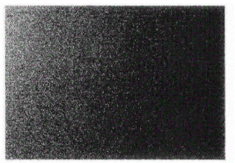
[0083] Figure 16 When the gap between the light source 4 and the bottom surface 1 of the optical lens is equal to 0.2 mm, the curved bottom surface 1 of the optical lens has no diffusion structure (such as Figure 8 The illuminance distribution diagram of the light when the optical lens is shown), there are obvious bright circles in this illuminance distribution diagram.

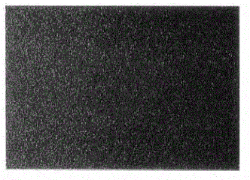
[0084] In this embodiment, Figure 17 When the gap between the light source 4 and the bottom surface 1 of the optical lens is equal to 0.2 mm, the illuminance distribution diagram of the light of th...

Embodiment 3

[0087] like Figure 18 As shown, in this embodiment, a light diffusing structure 5 with bumps is provided on the bottom surface 1 . When the light passes through the bottom surface 1, the light diffusion through the bump structure can solve the bright circle problem that occurs when the gap between the light source 4 and the bottom surface 1 of the optical lens is greater than 0.

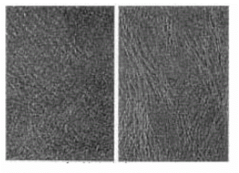
[0088] Figure 19It is the illuminance distribution diagram of light when the gap between the light source 4 and the bottom surface 1 of the optical lens is equal to 0.2 mm and the curved bottom surface 1 of the optical lens has no light diffusing structure 5 . It can be seen from the figure that when the light source 4 and the optical lens have packaging tolerances, and the bottom surface 1 of the optical lens is not provided with the light diffusing structure 5 , at this time, there are obvious bright circles on the light source receiving surface 6 .

[0089] Figure 20 When the gap between the...


PUM


Abstract

The invention discloses a large angle diffusing optical lens which is in rotational symmetry along a central axis. The optical lens is arranged above an optical source, the center of the optical lens and an optical source center are located on the same axis, the optical lens comprises a bottom surface, an arc light emitting surface and a light incoming surface with an arc concave middle, the arc light emitting surface is connected with one end of the bottom surface, the light incoming surface is connected with the other end of the bottom surface, the bottom surface is an annular concave curved surface which is connected with the arc concave light incoming surface, and a light diffusion structure is arranged on the annular concave curved surface of the bottom surface. According to the large angle diffusing optical lens, the light diffusion structure is arranged on the annular concave curved surface of the bottom surface so that light on an optical source receiving board can be uniformly distributed; the problem that bright rings are produced on a receiving surface due to packaging tolerance produced during packaging of the optical lens and the optical source can be prevented, and packaging tolerance requirements can be reduced; and the light diffusion structure can be arranged on the light emitting surface so that light on the optical source receiving surface can be uniformly distributed, and the problem of local bright rings on the optical source receiving surface can be solved.

Description

technical field [0001] The invention relates to a lens structure, in particular to a light-emitting device applied to a large-angle light-emitting device, in particular to a large-angle diffused optical lens in a backlight module using a dot-matrix backlight source. Background technique [0002] At present, the liquid crystal module used in the flat panel display mostly adopts the TFT-LCD (thin film field effect transistor LCD) technology. TFT-LCD is a non-active light-emitting display. Usually, a white backlight module (Backlight Module) provides uniform system brightness, and then a color filter (Color Filter) is used to obtain rich color display. [0003] like figure 1 As shown, the existing white light direct type backlight module includes a light source and an optical film set 6 . Light-emitting diode 4 (LED) has become one of the light sources used in the backlight module of liquid crystal display due to its small size and low energy consumption; LED4 is a Lambertian...

Claims


Application Information

Patent Timeline
Patent Type & Authority Applications(China)
IPC IPC(8): F21V5/04F21V17/00F21Y101/02
CPCG02B3/02G02B19/0019G02B19/0066H01L33/58
Inventor 李丽梅郑俊义林博瑛
Owner TPV DISPLAY TECH (XIAMEN) CO LTD
Why Eureka
Try Eureka