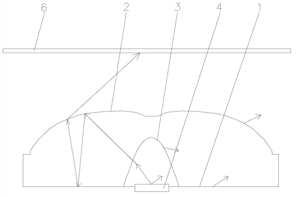
Large-angle diffusing optical lens
An optical lens, large-angle technology, applied in optics, lenses, condensers, etc., can solve problems such as bright circles and uneven light distribution, and achieve the effect of avoiding shadow shadows of support columns, uniform light distribution, and reducing packaging tolerance requirements.
- Summary
- Abstract
- Description
- Claims
- Application Information
AI Technical Summary
Problems solved by technology
Method used
Image
Examples
Embodiment 1
[0077] Such as Figure 13 As shown, the curved bottom surface 1 of the optical lens in this embodiment is an optical lens with a light diffusion structure 5 . Part of the light a is refracted outward when passing through the light-incident surface 3 , and refracted outward again when passing through the light-emitting surface 2 , so as to achieve the purpose of light diffusion. Part of the light b is reflected when it reaches the light-emitting surface 2, and when it reaches the bottom surface 1 of the curved surface, due to the influence of the curved surface structure, the light is reflected in a direction away from the central axis of the lens, which can reduce the light intensity near the central axis of the lens and make the receiving surface of the light source near the central axis The light on 6 is evenly distributed.
[0078] When the gap between the light emitting surface of the light source 4 and the bottom surface 1 of the light lens is greater than 0, since the c...
Embodiment 2
[0081] Such as Figure 15 As shown, in this embodiment, a light diffusion structure 5 with concave points is provided on the bottom surface 1 . When the light passes through the bottom surface 1, the light diffuses through the light diffusion structure 5 of the concave point, which can solve the problem of bright rings generated when the gap between the light source 4 and the bottom surface 1 of the optical lens is greater than 0.
[0082] Figure 16 When the gap between the light source 4 and the bottom surface 1 of the optical lens is equal to 0.2 mm, the curved bottom surface 1 of the optical lens has no diffusion structure (such as Figure 8 The illuminance distribution diagram of light when the optical lens is shown), there are obvious bright circles in this illuminance distribution diagram.
[0083] In this example, Figure 17 When the gap between the light source 4 and the bottom surface 1 of the optical lens is equal to 0.2 mm, the light illuminance distribution dia...
Embodiment 3
[0086] Such as Figure 18 As shown, in this embodiment, a light diffusion structure 5 with bumps is provided on the bottom surface 1 . When the light passes through the bottom surface 1, the light diffuses through the bump structure, which can solve the problem of bright circles generated when the gap between the light source 4 and the bottom surface 1 of the optical lens is greater than 0.
[0087] Figure 19When the gap between the light source 4 and the bottom surface 1 of the optical lens is equal to 0.2 mm, the illuminance distribution diagram of light when the curved bottom surface 1 of the optical lens has no light diffusion structure 5 . It can be seen from the figure that when there is a packaging tolerance between the light source 4 and the optical lens, and the bottom surface 1 of the optical lens is not provided with the light diffusion structure 5 , at this time, there are obvious bright circles on the light source receiving surface 6 .
[0088] Figure 20 When...
PUM
 Abstract
Description
Claims
Application Information
 - R&D
- Intellectual Property
- Life Sciences
- Materials
- Tech Scout
- Unparalleled Data Quality
- Higher Quality Content
- 60% Fewer Hallucinations
Browse by: Latest US Patents, China's latest patents, Technical Efficacy Thesaurus, Application Domain, Technology Topic, Popular Technical Reports.
© 2025 PatSnap. All rights reserved.Legal|Privacy policy|Modern Slavery Act Transparency Statement|Sitemap|About US| Contact US: help@patsnap.com


