
A vibrating meter including a damped meter component

A vibration meter and component technology, applied in the field of vibration meter, can solve the problem of limited frequency range of driving mode and so on

Active Publication Date: 2013-05-29
MICRO MOTION INC
View PDF5 Cites 2 Cited by
  • Summary
  • Abstract
  • Description
  • Claims
  • Application Information

AI Technical Summary

Problems solved by technology

Therefore, the frequency range available for drive mode is severely limited

Method used


Image

  • A vibrating meter including a damped meter component
  • A vibrating meter including a damped meter component
  • A vibrating meter including a damped meter component

Examples


Embodiment Construction

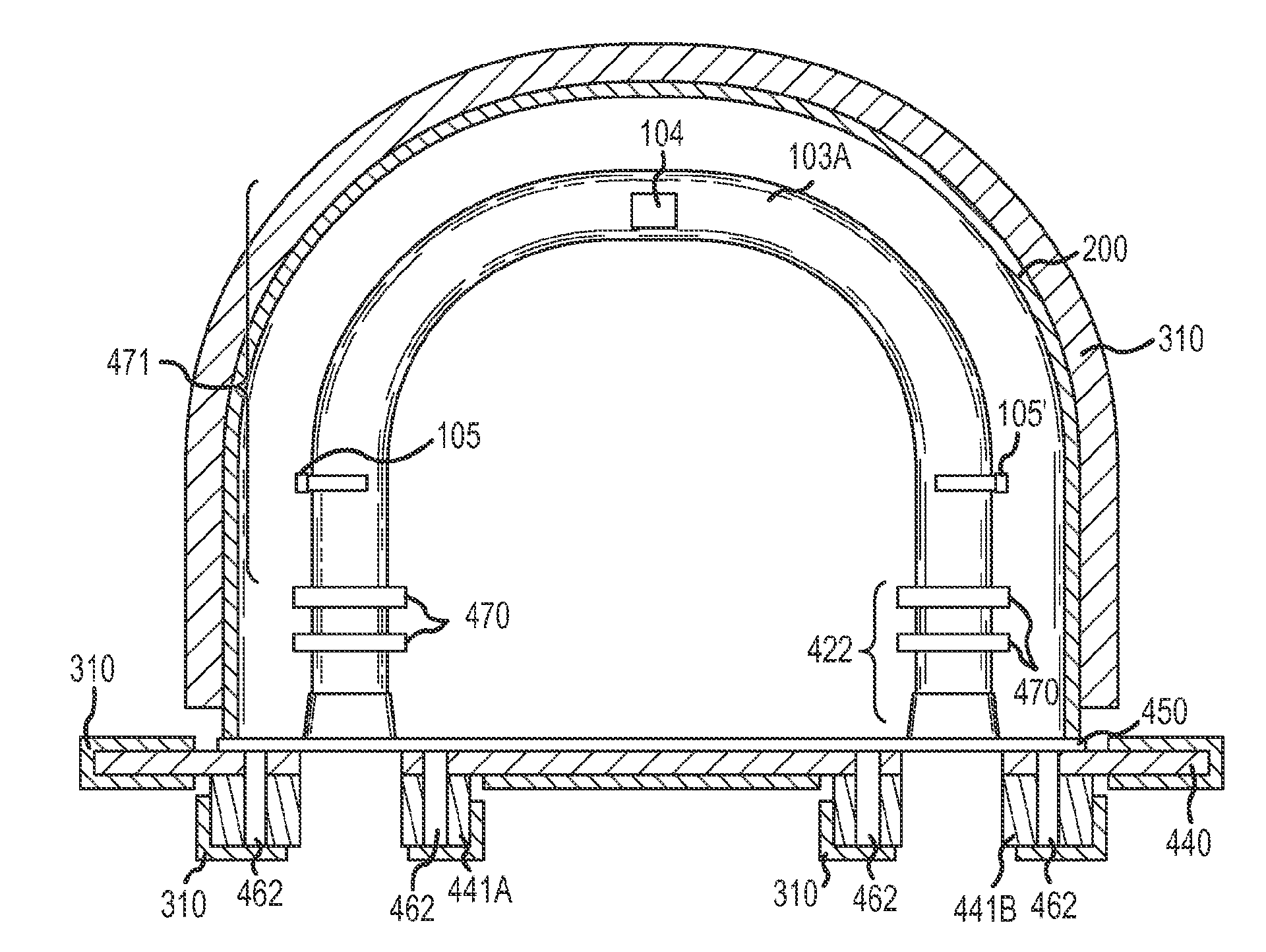
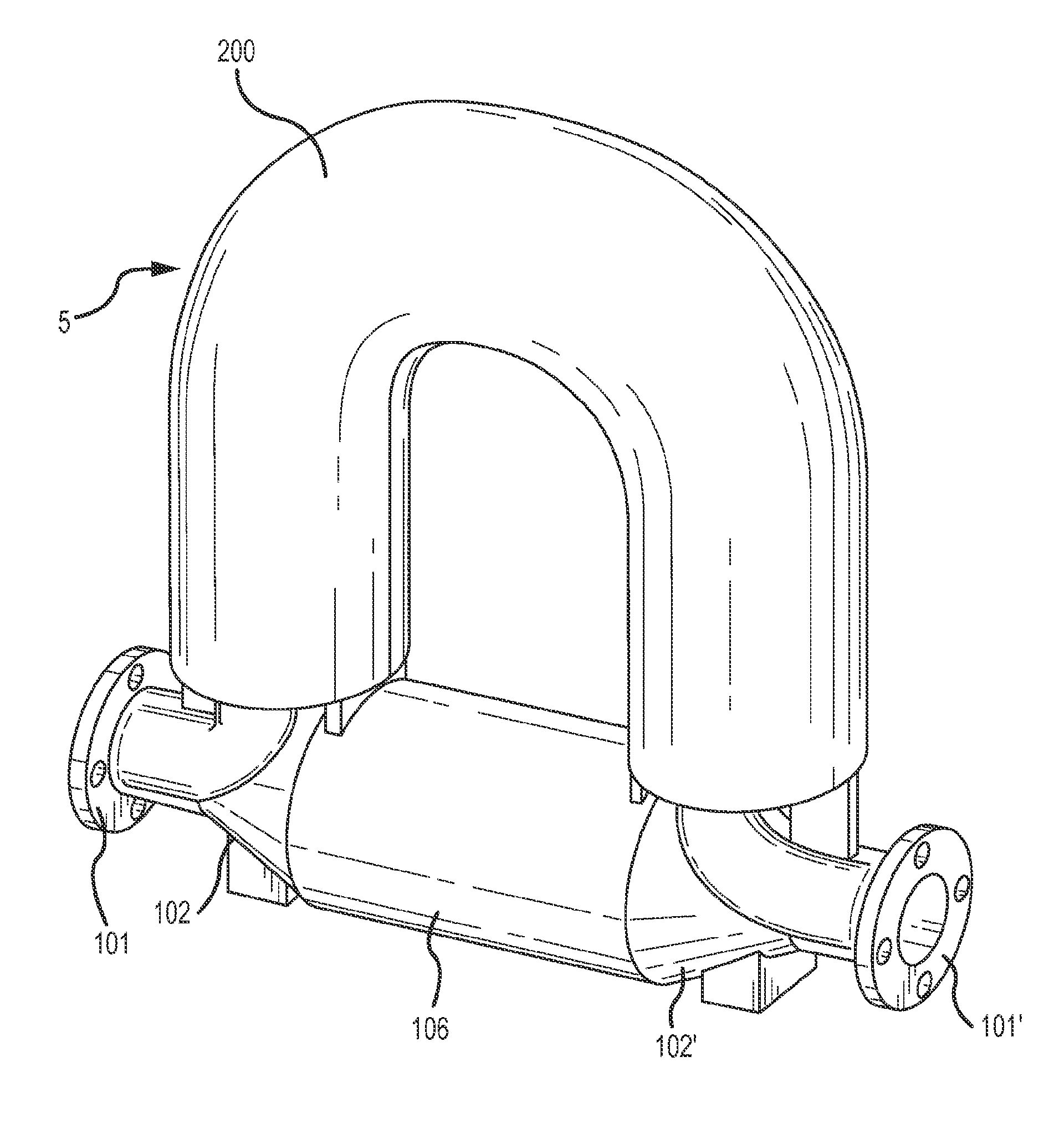
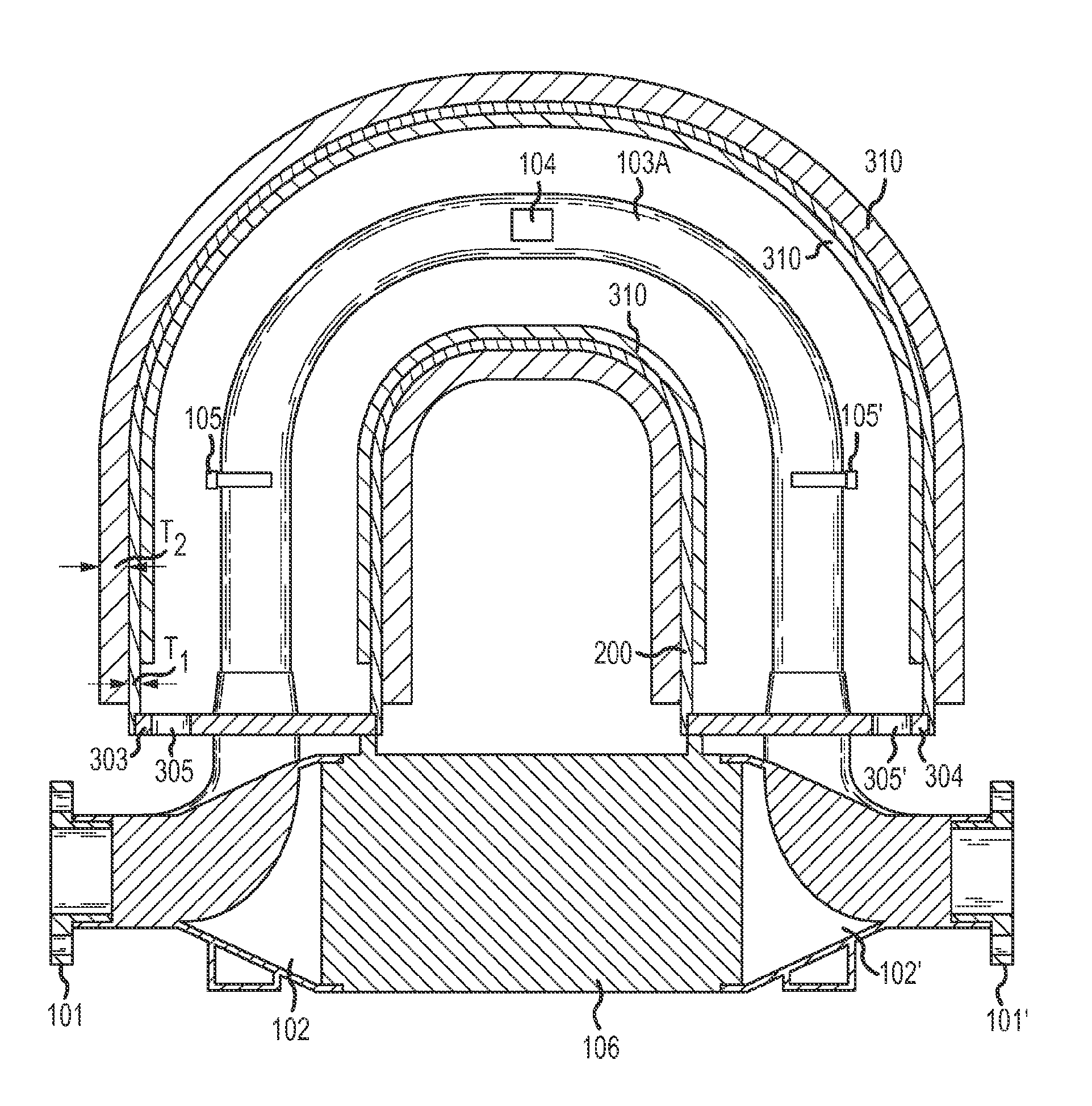
[0042] Figure 1-5 The following description and description describe specific examples to teach those skilled in the art how to make and use the best mode of the invention. Some routine content has been simplified or omitted in order to teach the principles of creativity. Those skilled in the art can appreciate various modifications from these examples that fall within the scope of the present invention. Those skilled in the art will appreciate that the features described below can be combined in various ways to form multiple variations of the invention. As a result, the invention is not to be limited by the specific examples described below, but only by the claims and their equivalents.

[0043] figure 1 A vibrating meter 5 is shown in meter form, comprising a sensor device 10 and one or more meter electronics 20 . The vibrating meter 5 may include a Coriolis flow meter, a volume flow meter, a density meter, and the like. Meter electronics 20 is connected to sensor dev...


PUM


Abstract

A vibrating meter (5) is provided. The vibrating meter (5) includes one or more conduits (103A, 103B) including a vibrating portion (471) and a non-vibrating portion (472) and a driver (104) coupled to a conduit of the one or more conduits (103A, 103B) and configured to vibrate the vibrating portion (471) of the conduit at one or more drive frequencies. The vibrating meter (5) also includes one or more pick-offs (105, 105') coupled to a conduit of the one or more conduits (103A, 103B) and configured to detect a motion of the conduit. One or more meter components exclusive of the vibrating portion (471) of the conduits (103A, 103B), the driver (104), and the pick-offs (105, 105') is provided with a damping material (310) applied to at least a portion of a surface of a meter component of the one or more meter components that reduces one or more vibrational resonant frequencies of the meter component below the one or more drive frequencies.

Description

technical field [0001] The present invention relates to vibrating meters, and more particularly to vibrating meter components having damping material applied to the surface of the metering component. Background technique [0002] Vibration meters such as density meters, volume flow meters and Coriolis flow meters are used to measure one or more properties of materials such as density, mass flow rate, volume flow rate, total mass flow rate, temperature and other information. The vibrating meter includes one or more conduits, which can have various shapes such as straight, U-shaped or irregular structures. [0003] One or more pipelines have a set of inherent modes of vibration including modes such as simple bending, torsional, radial and coupled vibrations. In order to determine the properties of the material, one or more conduits are vibrated by at least one drive at a resonant frequency in one of these modes, hereinafter referred to as drive mode. One or more meter electr...

Claims


Application Information

Patent Timeline
Patent Type & Authority Applications(China)
IPC IPC(8): G01F1/84
CPCG01F1/8472G01F1/8477G01F1/8413G01D11/00Y10T29/494G01F1/84
Inventor G.T.兰罕C.A.威尔巴赫
Owner MICRO MOTION INC
Learn More