Method for controlling gas backflow in melting reduction smelting

A technology of coal gas and cold gas, which is applied in the field of gas reverse channeling control in smelting reduction smelting, which can solve the problems of lower qualified rate of molten iron, fluctuation of factory pressure, fluctuation of gasifier furnace condition, etc., to reduce the probability of shaft furnace agglomeration, Improvement of operating rate and output and reduction of wind down time

Inactive Publication Date: 2013-07-03
CHINA BAOWU STEEL GRP CORP LTD
View PDF2 Cites 2 Cited by
  • Summary
  • Abstract
  • Description
  • Claims
  • Application Information

AI Technical Summary

Problems solved by technology

[0006] ①The addition of powdered ore in the center of the shaft furnace affects the gas permeability of the shaft furnace material column, and the pressure difference is high, which is not conducive to the full utilization of gas, and the metallization rate is reduced, which eventually leads to an increase in the fuel ratio
[0007] ②Powdered ore is added to the center of the shaft furnace, and the counter-channeling gas is suppressed. The counter-channeling gas flow of the 8 DRI downcomers (DRI, sponge iron, the same below) is uneven. The stronger the counter-channeling gas flow of a certain DRI downcomer, the corresponding The more dust is enriched at the DRI spiral, the higher the temperature and the dust background, the area is prone to sticking, and when the bonding material enters the downcomer through the spiral, the downcomer will be blocked.
[0008] ③After the downcomer is blocked, the material distribution of the melting and gasifier is uneven, which easily induces unfavorable conditions such as pressure fluctuations in the factory and output gas spikes, resulting in fluctuations in the furnace conditions of the gasifier and a decrease in the qualified rate of molten iron
In order to reduce the fluctuation of the gasifier, one downpipe is blocked, and the production can barely be maintained; if two are blocked, the wind must be shut down to clear the blockage, which affects the operation rate and production increase

Method used


Image

  • Method for controlling gas backflow in melting reduction smelting

Examples


Embodiment 1

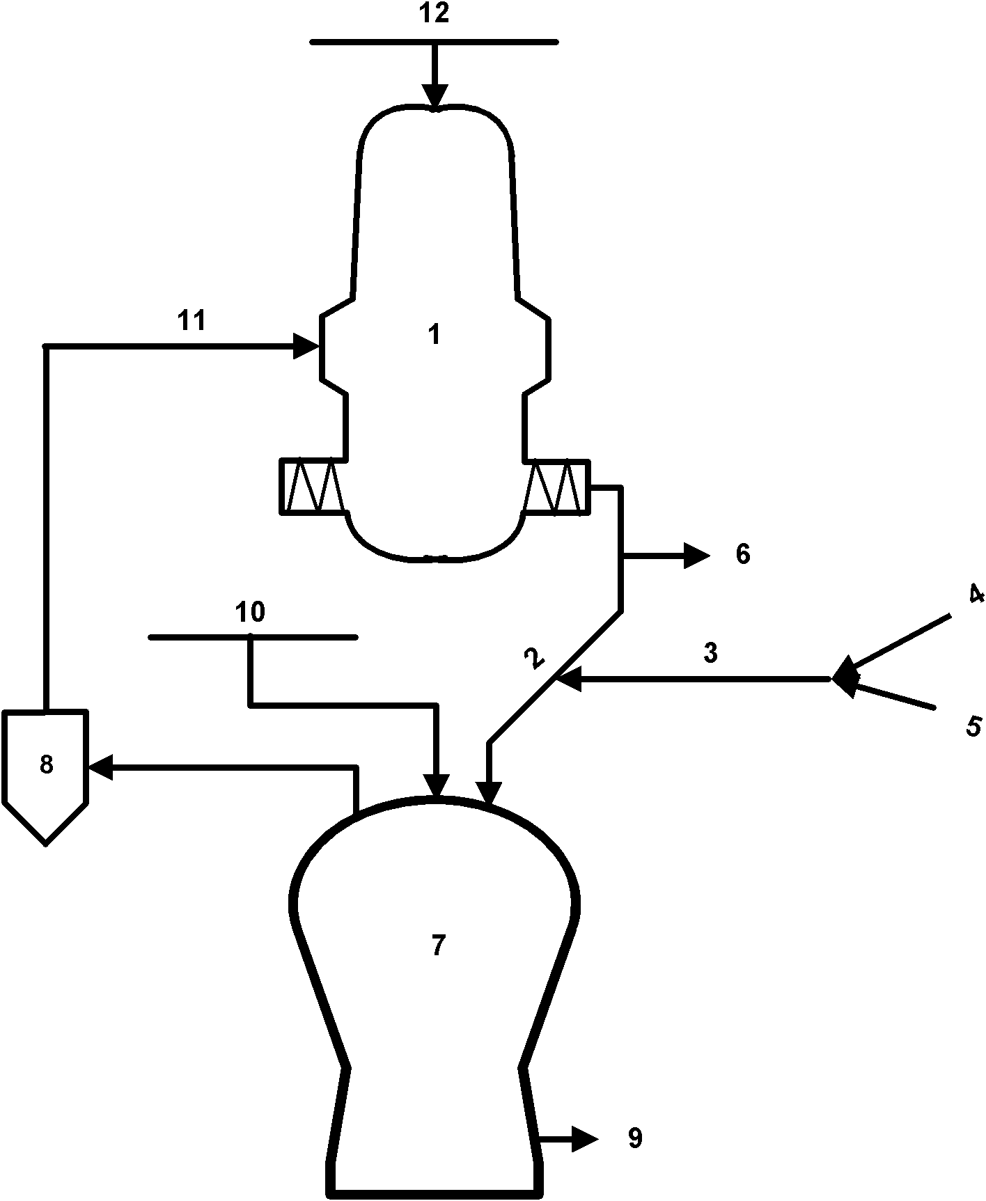
[0026] By adopting the method of the present invention, the powder addition in the center of the shaft furnace (0% powder addition) is cancelled, the cold gas is introduced into the cold gas pipeline 4, the temperature of the downcomer is controlled between 650~750°C, the melting rate is 138t / h, and the shaft furnace pressure The difference is 47kPa, the metallization rate is 65%, the average downcomer blockage is 1.1 times / month, the fuel ratio is 991kg / thm, and the coke ratio is 153kg / thm.

Embodiment 2

[0028] By adopting the method of the present invention, the addition of powder in the center of the shaft furnace (0% powder addition) is cancelled, cold gas is passed into the cold gas pipeline 4, nitrogen gas is passed into the nitrogen gas pipeline 5, and the temperature of the downcomer is controlled between 650 to 750°C. The rate is 138t / h, the pressure difference of the shaft furnace is 45kPa, the metallization rate is 57%, the downcomer blockage is 0.9 times / month on average, the fuel ratio is 1010kg / thm, and the coke ratio is 186kg / thm.


PUM


Abstract

The invention relates to a method for controlling gas backflow in melting reduction smelting. Each DRI downcomer connected with a shaft furnace is mounted with a cold gas and nitrogen adding pipe which is provided with a control valve. The DRI downcomer is mounted with a temperature detection galvanic couple to detect gas temperature in the downcomer. Through inputting cold gas or nitrogen to the DRI downcomer, the temperature of the backflow gas in the DRI downcomer is controlled at 650-750 DEG C. The high temperature backflow gas which does harm to shaft furnace running is transformed into normally used reduction gas, which participates in reduction inside the shaft furnace to achieve control of the gas backflow. Conventional practice of suppressing backflow gas is changed by the present invention, adding powder to shaft furnace center is cancelled, and the backflow gas is dredged and used. Cold gas/nitrogen is fed into the DRI downcomer to reduce the temperature of backflow gas, improve dust distribution and enrichment condition in the shaft furnace, reduce shaft furnace differential pressure, improve gas utilization, prolong shaft furnace emptying cycle, reduce downcomer blockage frequency and damping down time, and improve operation rate and yield.

Description

technical field [0001] The invention relates to a smelting reduction smelting process, in particular to a method for controlling gas backchanneling in smelting reduction smelting. Background technique [0002] The smelting reduction smelting process is world-renowned because it does not require sintering and coking processes, and is environmentally friendly. It is the smelting reduction ironmaking process that has been truly industrialized so far; this process divides the traditional blast furnace into two, and the upper half is a shaft furnace. The second half is the melting and gasification furnace, which completes the final smelting of molten iron; the shaft furnace and the gasification furnace are connected by 8 DRI downcomers, and the sponge iron produced by the shaft furnace pre-reduction is fed into the gasifier through the downcomers , The coal gas generated in the gasifier is fed into the shaft furnace as reducing gas after dedusting. [0003] There are following p...

Claims


Application Information

Patent Timeline
Patent Type & Authority Applications(China)
IPC IPC(8): C21B11/02C21B13/02
Inventor 谢学荣李晓清胡双柏梁利生朱锦明赵华盛宋文刚钱良丰徐辉王臣周海忠
Owner CHINA BAOWU STEEL GRP CORP LTD
Why Eureka
Try Eureka