Trigger type sparkgap and control method thereof

A spark gap and trigger control technology, applied in the field of electric equipment, can solve the problems of low stability and reliability of spark gap trigger discharge, unfavorable reliable operation of the gap, and high ignition discharge voltage, so as to improve the protection coordination performance and eliminate the polarity. effect, the effect of reducing the voltage value

Inactive Publication Date: 2013-07-10
CHINA ELECTRIC POWER RES INST +1
View PDF4 Cites 8 Cited by
  • Summary
  • Abstract
  • Description
  • Claims
  • Application Information

AI Technical Summary

Problems solved by technology

Through a lot of experimental research work, it is found that using a sealed gap in the trigger system can improve the trigger reliability of the gap system, but it has a serious polarity effect when the ignition discharge is only performed on the electrode on one side of the sealed gap, a voltage polarity The ignition discharge voltage under the polarity is very low, while the ignition discharge voltage under the other polarity is very high, and the delay is large, resulting in low stability and reliability of the trigger discharge of the spark gap; in addition, the current foreign series supply The spark gap provided above provides energy to the trigger control box in the form of laser energy delivery. This energy supply method is affected by many factors, which is not conducive to the reliable operation of the gap.

Method used


Image

  • Trigger type sparkgap and control method thereof

Examples


Embodiment Construction

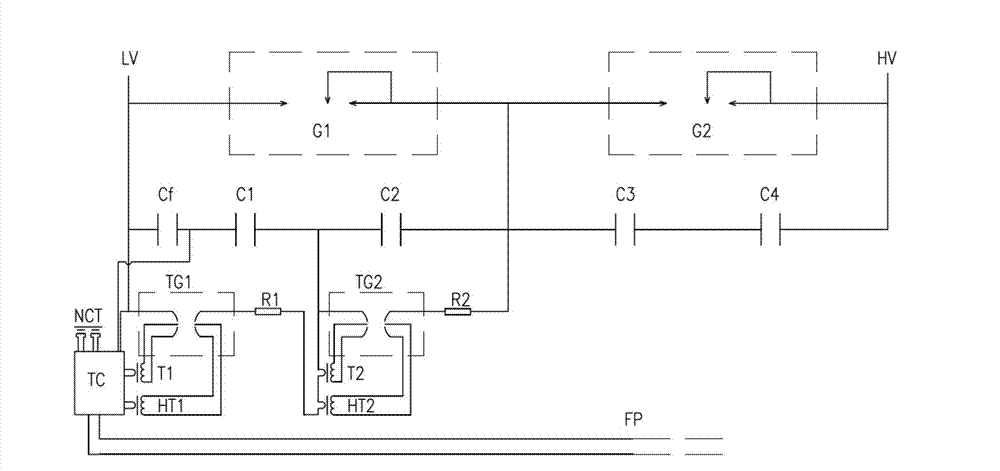
[0032] The specific implementation manners of the present invention will be further described in detail below in conjunction with the accompanying drawings.

[0033] The structural diagram of a triggered spark gap provided in this embodiment is as follows figure 1 As shown, it includes gap triggering system, self-discharging main gap G1, self-discharging main gap G2, voltage dividing capacitor Cf and voltage equalizing capacitors C1~C4, self-discharging main gap G1 and self-discharging main gap G2 are formed in series The main gap branch is connected to the low-voltage end and high-voltage end of the grid respectively; the voltage dividing capacitor Cf and the voltage equalizing capacitor are connected in parallel with the main gap branch; the gap trigger system is connected to the low-voltage end of the main gap branch. Self-discharge type main gap ( figure 1 In the self-discharge type main gap G1) in parallel.

[0034] Self-discharging main gaps include metal casings, flas...


PUM


Abstract

The invention discloses a trigger type sparkgap which comprises a gap triggering system, a self-discharge type main gap G1, a self-discharge type main gap G2, a voltage-dividing capacitor Cf and a voltage sharing capacitor. The self-discharge type main gap G1 and the self-discharge type main gap G2 are connected in series and form a main gap branch, the main gap branch is connected with a low-voltage end and a high-voltage end of a power grid respectively, the voltage-dividing capacitor Cf and the voltage sharing capacitor are connected in series and then are connected with the main gap branch in parallel, and the gap triggering system is in parallel connection with the self-discharge type main gap which is connected to the low-voltage end of the main gap branch. The gap triggering system comprises a trigger control (TC) box, and the TC box is powered by getting energy form a circuit through a current transformer (NCT) and communicates with the outside world through optical fiber (FP). The control method of the trigger type sparkgap is strong in practicality, and is proven in engineer. Further, the trigger type sparkgap is proven to be quite reliable in trigger discharge.

Description

technical field [0001] The invention belongs to the technical field of electric equipment, and in particular relates to a triggered spark gap and a control method thereof. Background technique [0002] Since 2001, many companies have independently developed complete sets of equipment for series compensation of AC transmission lines, among which spark gaps play an important role in the complete set of series compensation equipment. [0003] The spark gap generally consists of two main gaps in series to form a gap system. When the spark gap action is required to bypass the series compensation capacitor bank, the series compensation control and protection system sends a trigger command to the gap trigger control box through the optical fiber, and the gap trigger control box then gives the gap The system sends a trigger signal that eventually causes the spark gap to breakdown discharge, causing the spark gap to bypass the capacitor bank. Through a lot of experimental research w...

Claims


Application Information

Patent Timeline
Patent Type & Authority Applications(China)
IPC IPC(8): H01T2/00H01T14/00H01T15/00
Inventor 刘之方李国富董勤晓高克利余辉李志远
Owner CHINA ELECTRIC POWER RES INST
Why Eureka
Try Eureka