Exhaust gas cleaner

An exhaust purification device and electrode technology, which is applied to exhaust devices, mufflers, chemical instruments and methods, etc., can solve the problems of voltage waveform and current waveform deviation, lack of control and collection, large power consumption, etc., and achieves reactance fluctuations. Reduce, realize energy utilization, reduce the effect of digesting power

Inactive Publication Date: 2008-05-21
HINO MOTORS LTD
View PDF1 Cites 10 Cited by
  • Summary
  • Abstract
  • Description
  • Claims
  • Application Information

AI Technical Summary

Problems solved by technology

[0015] However, in the conventional plasma-assisted exhaust purification device, if a high voltage is always applied to the inner electrode and the outer electrode, the power consumption will be excessively large.
[0016] In addition, when the electric power for discharging is alternating current, a circuit in which a high voltage is applied to a capacitor composed of outer and inner electrodes is regarded as an equivalent circuit. Changes in components, etc., so the reactance of the circuit can be expected to fluctuate, resulting in deviations in the voltage waveform and current waveform, and power reduction
[0017] Moreover, in the conventional plasma-assisted exhaust purification device, it is not possible to grasp how many particles are actually collected.

Method used


Image

  • Exhaust gas cleaner
  • Exhaust gas cleaner
  • Exhaust gas cleaner

Examples


Embodiment 1

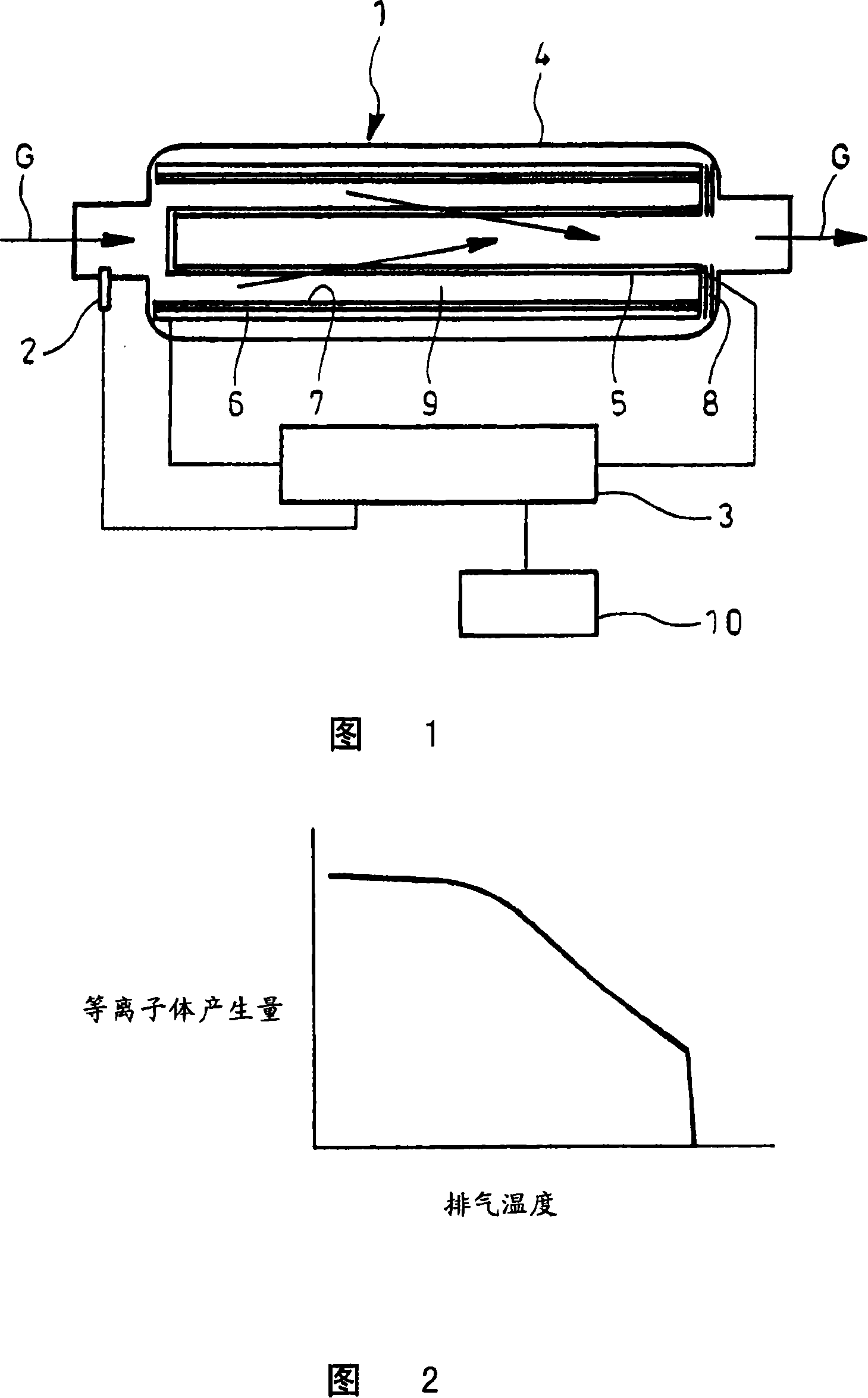
[0079] 1 and 2 show a first embodiment of the exhaust gas purification device of the present invention, this exhaust gas purification device is equipped with a collection chamber 1, a temperature sensor 2, and a discharge control unit 3.

[0080] The collection chamber 1 is provided with: a casing 4 assembled in the flow path of the exhaust gas G to be purified; a hollow inner electrode 5 formed of a conductive filter capable of collecting particles, The inside of the casing is arranged coaxially; the cylindrical outer electrode 6 is arranged inside the case 4 so as to surround the inner electrode 5 in the circumferential direction; a dielectric body 7 such as ceramics covers the outer electrode 6 The inner surface.

[0081] Further, a particulate filter to which cordierite or the like is applied is provided separately from the collecting chamber 1 in the flow path of the exhaust gas G.

[0082] As the above-mentioned conductive filter, there is a form integrated by laminatin...

Embodiment 2

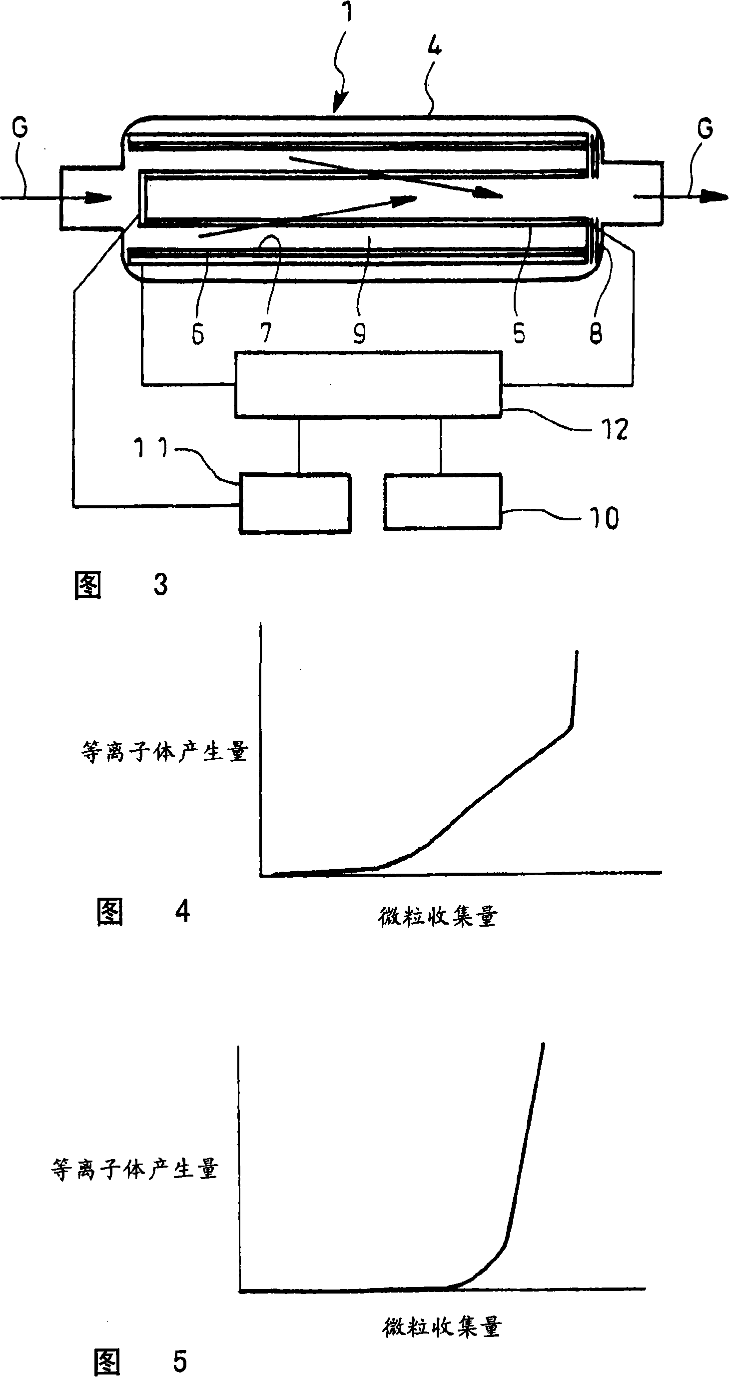
[0097] 3 to 5 show the second embodiment of the exhaust gas purification device of the present invention. This exhaust gas purification device is equipped with a collection chamber 1, a collection amount estimation mechanism 11, and a discharge control unit 12. The collection chamber 1 and the vehicle-mounted power supply 10 It has the same structure as that shown in Figure 1.

[0098] The amount of collection estimation mechanism 11 measures parameters such as the internal pressure of the housing 4 and the electrical characteristics of the inner electrode 5 (voltage value, current value, and impedance value when energized), based on the collection amount of particles of the inner electrode 5 obtained through actual measurement in advance and The correlation of the measured values ​​of the parameters is used to calculate the particle collection amount of the inner electrode 5 at that moment.

[0099] The discharge control unit 12 is connected to an on-vehicle power supply 10 a...

Embodiment 3

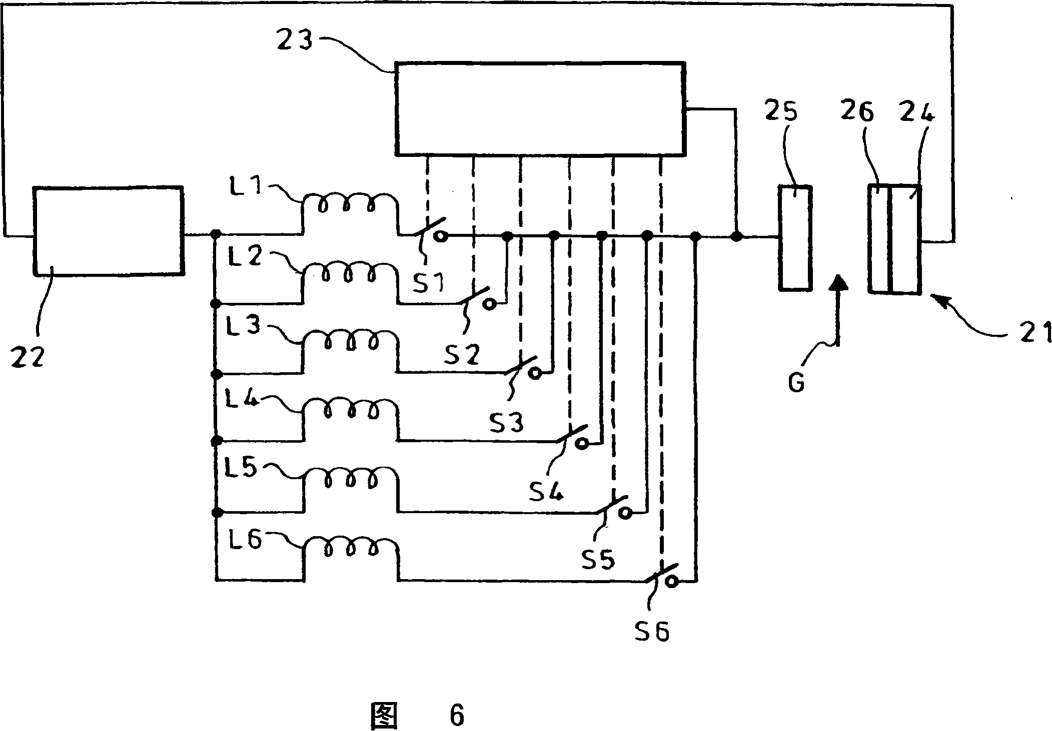
[0111] Fig. 6 shows the third embodiment of the exhaust purification device of the present invention. This exhaust purification device is equipped with a collection chamber 21, a high voltage output mechanism 22 for outputting alternating current for discharge, a plurality of inductors L1-L6, and an inductance coefficient Control mechanism 23.

[0112]The collection chamber 21 is equipped with: a pair of electrodes 24, 25, which are arranged in the flow path of the exhaust gas G to be purified; a dielectric body 26 such as ceramics, which covers one electrode 24, and can collect particles due to its conductivity. The filter constitutes the other electrode 25 .

[0113] The shape of these electrodes 24 and 25 may be any of a cylindrical shape, a flat-plate opposing shape, or a lattice shape.

[0114] As the above-mentioned conductive filter, there is a form integrated by laminating and sintering fibrous metal, a form of integrating a sintered body of metal powder and a fine me...


PUM


Abstract

Provided are a hollow inner electrode 5 constituted by an electrically conductive filter capable of capturing particulates, a cylindrical outer electrode 6 circumferentially surrounding the electrode 5, a housing 4 incorporated in a flow passage of exhaust G and accommodating the electrodes 5 and 6, a temperature sensor 2 for detecting temperature of the exhaust G and an electric discharge controller 3 for controlling electric power to be distributed to the electrodes 5 and 6 on the basis of a detected value of the temperature sensor 2 . When the temperature of the exhaust G obtained by the temperature sensor 2 is lowered, electric power necessary for generation of discharge plasma is distributed by the discharge controller 3 to the electrodes 5 and 6, thereby oxidizing the particulates captured by the electrode 5 to reduce electricity consumption.

Description

technical field [0001] The invention relates to an exhaust purification device. Background technique [0002] Diesel engine exhaust (diesel combustion gas) contains carbonaceous coal and SOF (Soluble Organic Fraction: soluble organic fraction) composed of carbonaceous hydrocarbon components as main components, and a small amount of sulfuric acid is added Particles (Particulate Matter: particulate matter) composed of salt (fog-like sulfuric acid component). [0003] In order to suppress the diffusion of such particles into the atmosphere, a filter for collecting particles is often installed in the exhaust system of the engine. [0004] As an example of such a particulate filter, there is a form in which a honeycomb mandrel is formed of ceramics such as cordierite, and exhaust gas from an engine flows through a plurality of passages separated by porous thin walls of the honeycomb mandrel. [0005] In the above-mentioned particulate filter, every other end portion of a plural...

Claims


Application Information

Patent Timeline
Patent Type & Authority Applications(China)
IPC IPC(8): F01N3/01F01N3/02F01N3/08B01D46/42B03C3/49B03C3/68
CPCB03C3/366B03C2201/30B03C3/49
Inventor 下田正敏町田耕一古川卓俊
Owner HINO MOTORS LTD
Why Eureka
Try Eureka