
Multiple contact connector

a contact connector and connector technology, applied in the direction of coupling device connection, two-part coupling device, electrical apparatus, etc., can solve the problem of interference with the matching of impedances with the device, and achieve the effect of suppressing the reduction of impedance values

Active Publication Date: 2014-06-24
MOLEX INC
View PDF15 Cites 5 Cited by
  • Summary
  • Abstract
  • Description
  • Claims
  • Application Information

AI Technical Summary

Benefits of technology

The design allows for a compact multiple contact connector that suppresses impedance reduction during high-speed transmission, maintaining effective signal transmission speed by controlling capacitance and impedance matching.

Problems solved by technology

On the other hand, device miniaturization necessitates miniaturization of the contacts themselves, where simply making the multiple contact connector smaller would reduce the distances between the contacts, which would reduce the impedance value, at the time of high-speed transmission, through forming capacitances between the contacts, which would interfere with the matching of impedances with the device.

Method used


Image

  • Multiple contact connector
  • Multiple contact connector
  • Multiple contact connector

Examples


Embodiment Construction

[0020]While the Present Disclosure may be susceptible to embodiment in different forms, there is shown in the Figures, and will be described herein in detail, specific embodiments, with the understanding that the Present Disclosure is to be considered an exemplification of the principles of the Present Disclosure, and is not intended to limit the Present Disclosure to that as illustrated.

[0021]As such, references to a feature or aspect are intended to describe a feature or aspect of an example of the Present Disclosure, not to imply that every embodiment thereof must have the described feature or aspect. Furthermore, it should be noted that the description illustrates a number of features. While certain features have been combined together to illustrate potential system designs, those features may also be used in other combinations not expressly disclosed. Thus, the depicted combinations are not intended to be limiting, unless otherwise noted.

[0022]In the embodiments illustrated in ...


PUM


Abstract

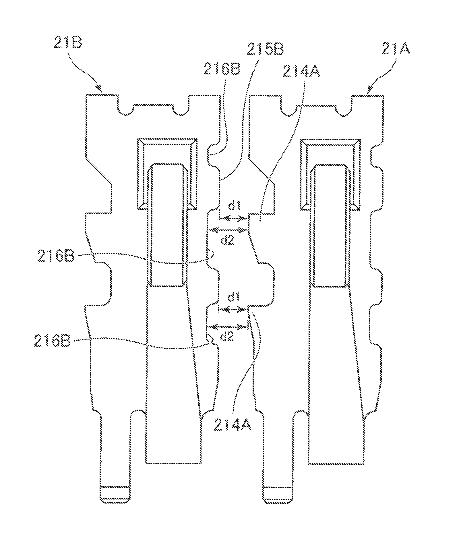
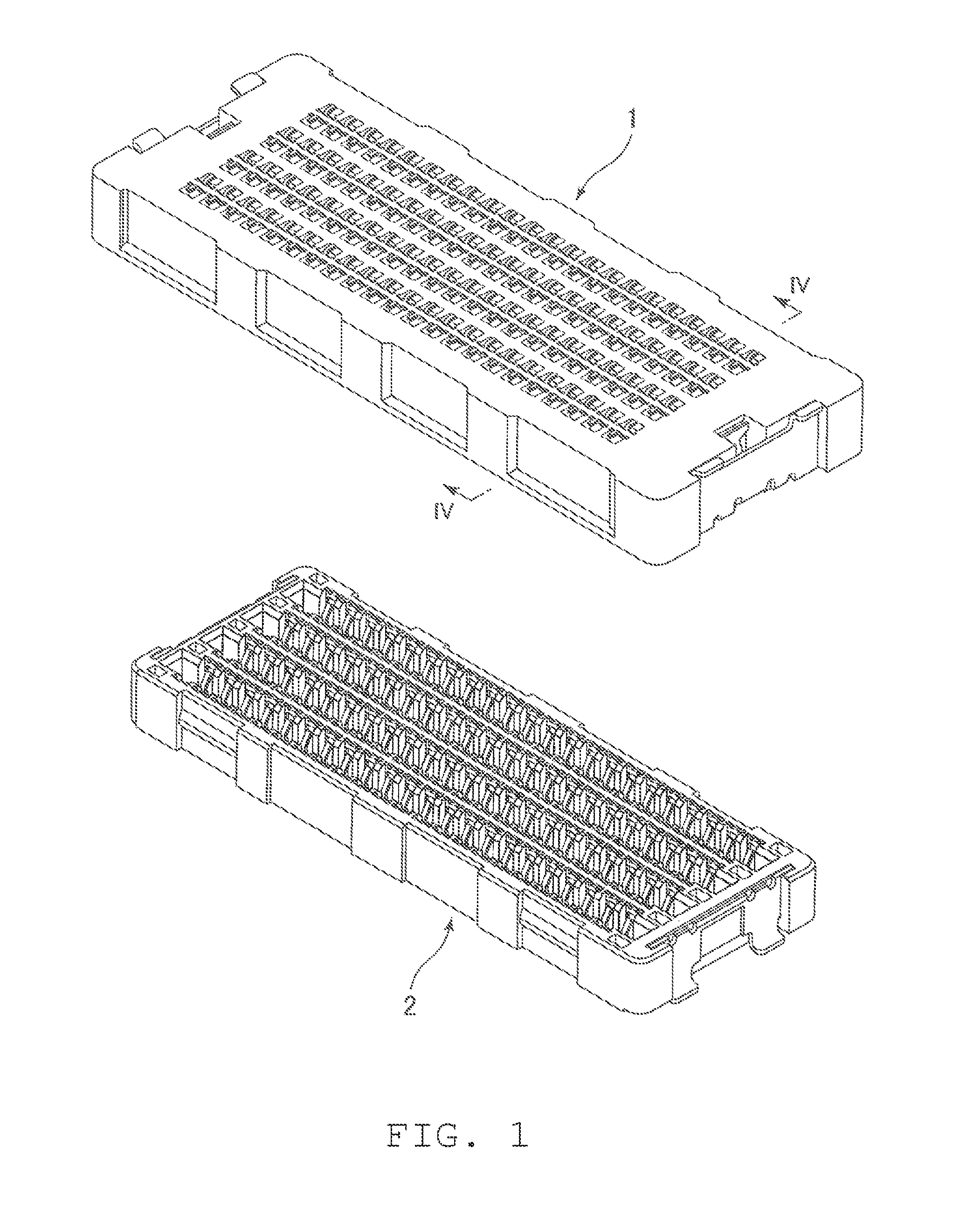
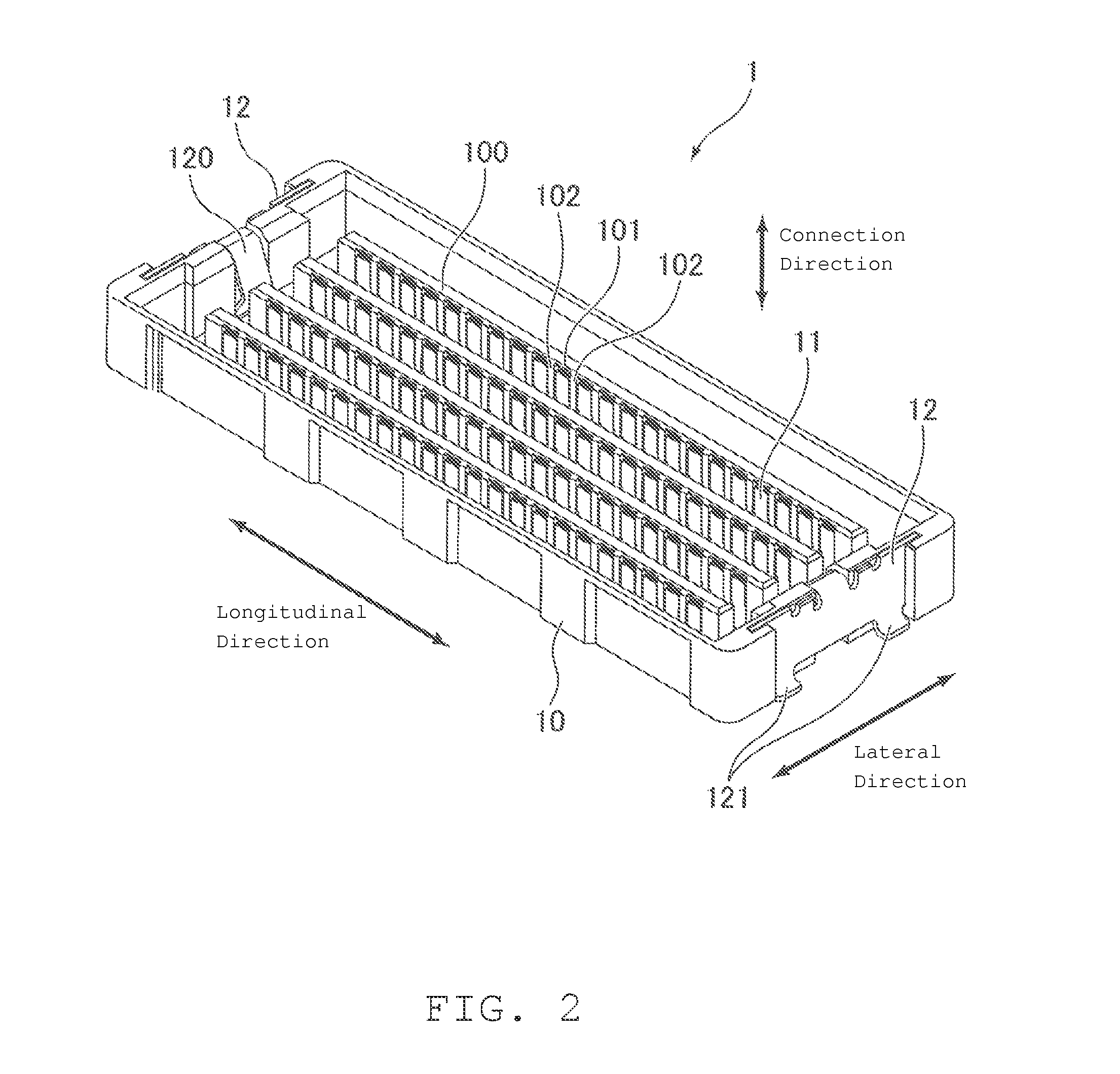
A multiple contact connector comprises a plurality of terminal pieces arranged linearly in the lengthwise direction, and an insulating provided with a plurality of dividing walls extending between the terminal pieces for supporting the terminal pieces and for insulating between adjacent terminal pieces, having the insulating pieces inserted into terminal supporting spaces between the separating walls.

Description

REFERENCE TO RELATED APPLICATIONS[0001]The Present Disclosure claims priority to prior-filed Japanese Patent Application No. 2011-155952, entitled “Multiple Contact Connector,” filed on 14 Jul. 2011 with the Japanese Patent Office. The content of the aforementioned Patent Application is incorporated in its entirety herein.BACKGROUND OF THE PRESENT DISCLOSURE[0002]The Present Disclosure relates, generally, to a multiple contact connector, and, more particularly, to a multiple contact connector that is small and that is able to suppress a reduction in the impedance value at the time of high-speed transmission.[0003]When transmitting data via signal lines, the value of the impedance at the connecting portion of a connector, that connects between a signal line and a device has an effect on the transmission speed. In particular, if the impedance of the connecting portion on the signal receiving side does not match that of the device side when performing high-speed transmissions, then the...

Claims


Application Information

Patent Timeline
Patent Type & Authority Patents(United States)
IPC IPC(8): H01R24/00
CPCH01R24/60H01R12/716H01R13/6474
Inventor NAGASE, TERUKIMATSUSHITA, HIDEHIROCHIKANO, KOJIYAGI, MASANORI
Owner MOLEX INC
Learn More