Combined antenna formed by horizontal directivity antenna and zenithal directivity antenna

A combination antenna, horizontal direction technology, applied in antenna combinations with different interactions, suitable for antennas on movable objects, mid-position feed between antenna endpoints, etc., can solve problems such as inability to obtain operation

Inactive Publication Date: 2005-09-14
DENSO CORP
View PDF1 Cites 5 Cited by
  • Summary
  • Abstract
  • Description
  • Claims
  • Application Information

AI Technical Summary

Problems solved by technology

Satisfactory operation will not be obtained if the same ground plane is used by both an inverse Fourier antenna and an antenna directional in the meridian direction

Method used


Image

  • Combined antenna formed by horizontal directivity antenna and zenithal directivity antenna
  • Combined antenna formed by horizontal directivity antenna and zenithal directivity antenna
  • Combined antenna formed by horizontal directivity antenna and zenithal directivity antenna

Examples


no. 2 example

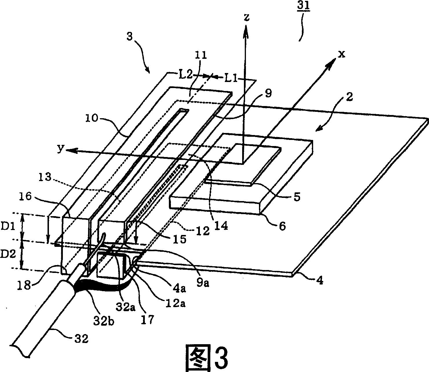
[0033] A second embodiment will be described with reference to FIGS. 3 and 4 . Components of the second embodiment corresponding to the first embodiment are designated by the same reference numerals, respectively, and further description thereof will be omitted. The second embodiment differs from the embodiment only in the way the coaxial cable is connected to the modified folded dipole antenna 3 . Specifically, for the second embodiment, the central conductor 32a of the coaxial cable 32 is connected to the tip 9a of the laterally extending portion 9 shown in FIG. ground plate4.

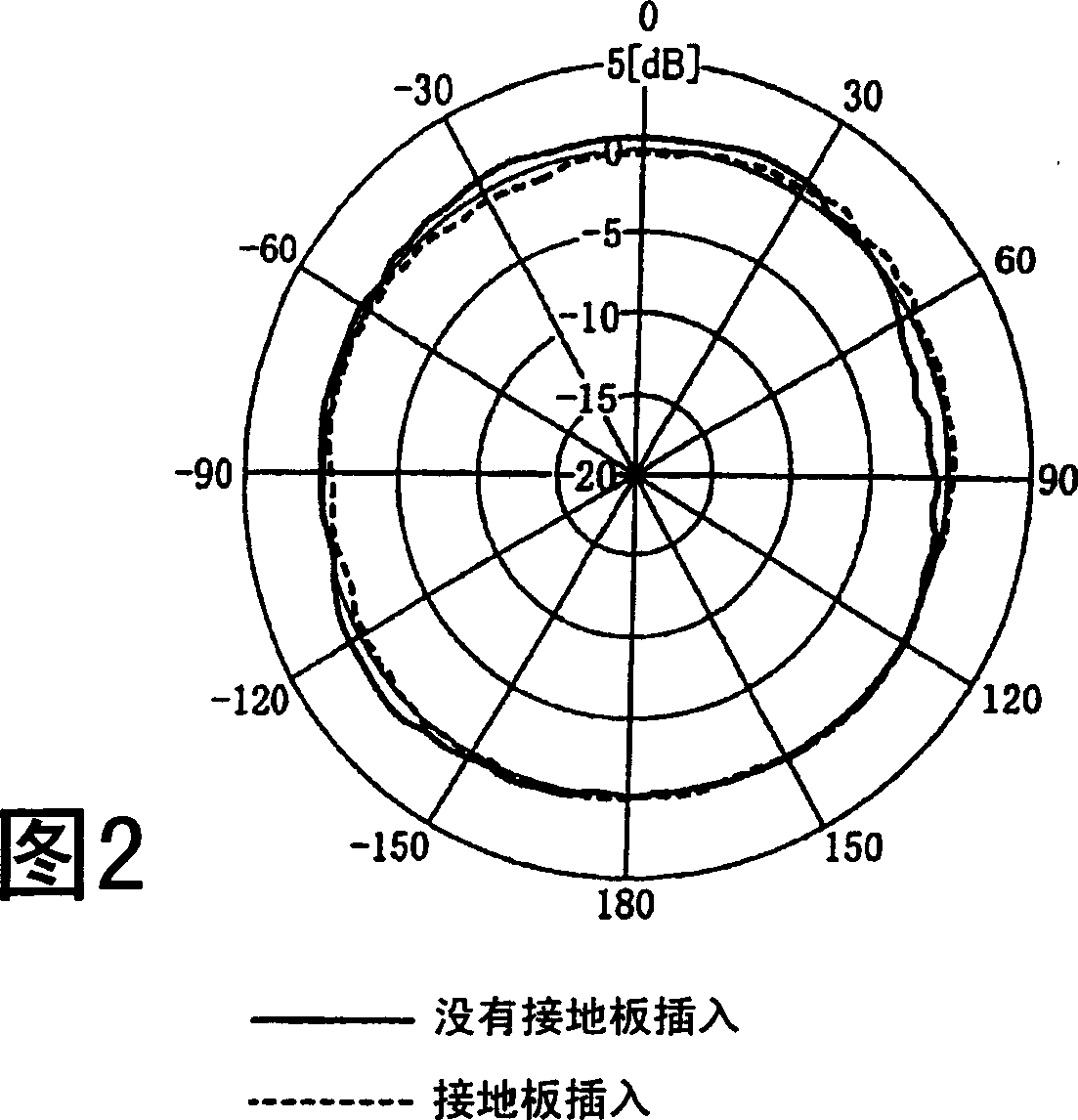
[0034] In the case where the outer conductor of the coaxial cable is connected to the modified folded dipole antenna (i.e., the inner conductor of the outer conductor is connected as shown in Figure 3), and the outer conductor of the coaxial cable is not connected to the modified In the case of the improved folded dipole antenna 3 of the present invention, the assignee of the present invention meas...

no. 3 example

[0037] will refer to Figure 5 A third embodiment will be described. Parts of the third embodiment corresponding to the first or second embodiment are designated by the same reference numerals, respectively, and further description thereof will be omitted, and only differences from the previous embodiments will be described.

[0038] Each of the first and second embodiments uses a modified folded dipole antenna as the antenna having directivity in the horizontal direction. For the third embodiment, a modified dipole antenna (ie, it does not include a folded structure) is used as the antenna having directivity in the horizontal direction. Specifically, if Figure 5 As shown, the combined antenna 41 of the third embodiment is composed of a modified dipole antenna 41 and a patch antenna 2, and the structure of the patch antenna 2 is the same as that of the previous embodiment. Antenna 42 is a transmission line antenna consisting of two elements 43 and 44 as shown. The element...


PUM


Abstract

A combined antenna is composed of a first antenna having directivity in a roof direction, a ground plate grounded as the first antenna and a second antenna having directivity in a horizontal direction. The second antenna as an improved dipole antenna has an upper and a lower arm parts which extend in parallel to the ground plate. At least a part of the ground plate is included in the arm parts of the second antenna.

Description

technical field [0001] The present invention relates to a combination antenna, which is composed of a first antenna having directivity in a predetermined direction, a ground plate as the ground of the first antenna, and a second antenna having directivity in the horizontal direction. Background technique [0002] In the prior art, there are examples of combined antennas in which a plurality of antennas share a common ground plane, such as the example described in Published Japanese Patent Document 2003-168917. However, in this prior art type combined antenna, each sub-antenna has directivity in the meridian direction, ie, has an elevation angle of about 90°, so each antenna can use a separate ground plane as a common ground. In recent years, with the development of wireless communication technology, combined antennas are required to be able to combine antennas with directivity in the meridian direction and antennas with directivity in the horizontal direction (that is, with ...

Claims


Application Information

Patent Timeline
Patent Type & Authority Applications(China)
IPC IPC(8): H01Q21/29H01Q1/32H01Q5/00H01Q9/16H01Q13/08H01Q21/00
Inventor 大原克博山崎徹林昭彦三上成信
Owner DENSO CORP
Why Eureka
Try Eureka