Dispense volume monitor for arrays

a technology of arrays and volume monitors, which is applied in the field of array volume monitors, can solve the problems of inaccurate volume droplets, small amount of liquid lost, inaccurate volume determination, etc., and achieve the effect of accurate volume determination, low output impedance values, and low channel numbers

Active Publication Date: 2010-09-16
BECTON DICKINSON & CO
View PDF9 Cites 6 Cited by
  • Summary
  • Abstract
  • Description
  • Claims
  • Application Information

AI Technical Summary

Benefits of technology

[0014]Another embodiment of the present invention provides electrical circuitry for a two-dimensional array of dispense volume monitors allowing interrogation of all wells in a two-dimensional array within a short period of time. This may be achieved either by applying an RF drive signal simultaneously to all upper electrodes in the array, and interrogating the lower electrodes via a low input impedance multiplexer, or by applying an RF drive signal in a serial mode of operation to all upper electrodes in the array via a low output impedance demultiplexer, and connecting all lower electrodes in parallel with an RF detector.
[0015]A further embodiment of the present invention provides electrical circuitry for a two-dimensional array of dispense volume monitors allowing interrogation of all wells in a two-dimensional array with a demultiplexer and multiplexer of relatively low channel numbers.
[0016]This may be achieved by applying an RF drive signal in a mixed mode of operation to all upper electrodes in the array via a demultiplexer with relatively low output impedance values and having a low number of channels addressing one row at a time, whereby all electrodes in a row are connected with each other, and interrogating the lower electrodes via a multiplexer with relatively low input impedance values and having a low number of channels addressing one column at a time, whereby all electrodes in a column are connected with each other.
[0017]A further embodiment provides a method for accurately determining the volume of liquid reagents actually dispensed into each well in a test plate, including the steps of inserting a first electrode into a container, wherein the container comprises a dispensed liquid sample volume, and a second electrode is arranged adjacent to the lower outside of the container, thereby forming a capacitor, and measuring the capacitance of the capacitor. The capacitance value of the dispensed liquid sample volume and the volume of the dispensed liquid sample are determined by comparing the capacitance value of the dispensed liquid sample volume with a calibration capacitance value. The calibration capacitance value is a capacitance value for a known dispensed liquid sample volume. The capacitance value of the dispensed liquid sample volume is calculated by subtracting a reference capacitance value from the measured capacitance value, wherein the reference capacitance value is the capacitance value of the capacitor with no liquid sample present in the container. A processor can be used to compare the capacitance value of the dispensed liquid sample volume with the calibration capacitance value, calculate the capacitance value of the dispensed liquid sample volume and calculate the volume of the dispensed liquid.

Problems solved by technology

However, the accurate determination of volume actually dispensed into each of the individual wells in an array still remains a problem.
However, the amount of liquid actually reaching the receiving well may vary, because part of the liquid leaving the inner needle space is creeping along the outer diameter of the dispensed needle, therefore forming a small amount of liquid that is lost from the particular dispense act.
It is also likely that such liquid may join the dispensed liquid in a dispensing step that follows the aspiration step, creating a droplet of incorrect volume.

Method used


Image

  • Dispense volume monitor for arrays
  • Dispense volume monitor for arrays
  • Dispense volume monitor for arrays

Examples


Embodiment Construction

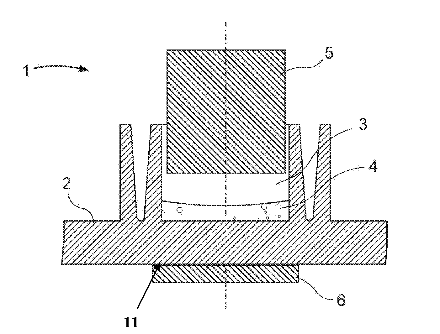
[0048]In needle-based dispensing systems, the targeted amount of liquid leaving the inner needle space is, in many cases, very well controlled, e.g. by the specific motion of a dispensing piston, by utilizing specialized pumps with accurate dosing capability, or by application of piezo-electric devices producing a defined volume displacement. However, the amount of liquid actually reaching the receiving well may vary, because part of the liquid leaving the inner needle space is creeping along the outer diameter of the dispensed needle, therefore forming a small amount of liquid that is lost from the particular dispense act. This occurrence may repeat itself in one or more successive dispense acts and a substantial amount of liquid may, consequently, accumulate on the outer needle diameter. Once a critical amount of liquid accumulates, this liquid will join a dispensed droplet, generating an actual dispensed volume that significantly exceeds the targeted dispensed volume.

[0049]In cer...


PUM


Abstract

The reagent volume dispensed into wells (3) of a test plate (2) is determined by moving an upper electrode (5) of specific profile into each well to an optimum position above the well bottom, by determining the capacitance value of the capacitor formed by the upper electrode in each well and a lower electrode (6) arranged adjacent to the lower outside surface (11) of the test plate below each well, and by comparing the measured capacitance value with reference calibration values.

Description

FIELD OF THE INVENTION[0001]The present invention relates to methods and apparatus for accurately dispensing a predetermined small volume of liquid reagents into open containers. In one embodiment, the present invention relates to methods and apparatus for determining the volume of liquid reagents that are dispensed into two-dimensional arrays of open wells.BACKGROUND OF THE INVENTION[0002]The dispensing of small volume reagent droplets with high accuracy represents an important process step in the production of medical diagnostic assays which are frequently based on using two-dimensional arrays of open wells, such as microtiter plates. Some examples of such dispense systems in use are described in the following references: U.S. Pat. No. 4,107,658, U.S. Pat. No. 4,196,615, U.S. Pat. No. 4,417,473, U.S. Pat. No. 4,818,492, U.S. Pat. No. 5,304,347, U.S. Pat. No. 5,601,980, U.S. Pat. No. 6,029,896, U.S. Pat. No. 6,148,666, U.S. Pat. No. 6,213,354, U.S. Pat. No. 6,551,558, U.S. Pat. No....

Claims


Application Information

Patent Timeline
Patent Type & Authority Applications(United States)
IPC IPC(8): G01F23/26
CPCB01L3/5085B01L2200/143B01L2300/0645G01N35/1016G01F23/263G01F23/268B01L2300/0829
Inventor BERNDT, KLAUS W.JAUNZEMIS, ANDRIS J.
Owner BECTON DICKINSON & CO
Why Eureka
Try Eureka