Control unit for an electric machine

a technology of control unit and electric machine, which is applied in the direction of electric variable regulation, process and machine control, instruments, etc., can solve the problems of destroying the power output stage or the driver unit of the power output stag

Active Publication Date: 2014-02-06
SEG AUTOMOTIVE GERMANY GMBH
View PDF3 Cites 9 Cited by
  • Summary
  • Abstract
  • Description
  • Claims
  • Application Information

AI Technical Summary

Benefits of technology

[0018]The previously described control using the temperature sensor which can detect the voltage transients advantageously controls the temperature of the intermediate circuit capacitor not as a function of the absolute temperature of the intermediate circuit capacitor but rather advantageously as a function of an undesirable effect of a temperature of the intermediate circuit capacitor. A correlation of the actual series resistance of the intermediate circuit capacitor as a function of the temperature or an absolute temperature of said intermediate circuit capacitor advantageously does not need to be known because the control operation for increasing the temperature can take place until the undesirable effects, namely the voltage transients, have fallen below a predetermined value. The voltage transients, which can produce damage to the on-board power supply when a predetermined value has been exceeded, are thus advantageously held at a harmless low voltage value and also serve as control parameters for an adjustment of the current application pattern, in particular of the pulse width modulation pattern, which has an effect on the heat generated in the intermediate circuit capacitor.

Problems solved by technology

Said high voltage peaks can destroy the power output stage or a driver unit of the power output stage.

Method used


Image

  • Control unit for an electric machine
  • Control unit for an electric machine
  • Control unit for an electric machine

Examples


Embodiment Construction

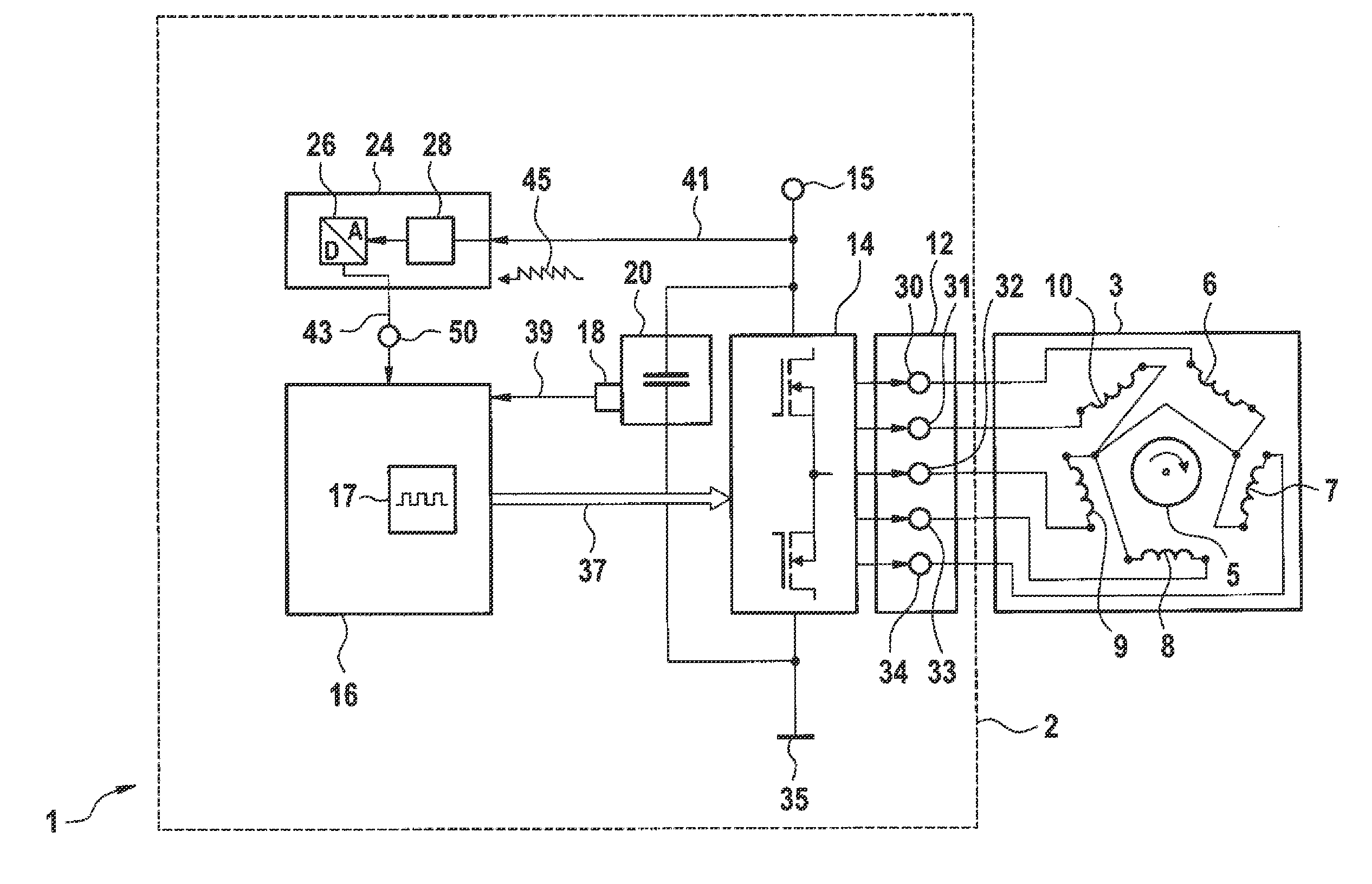
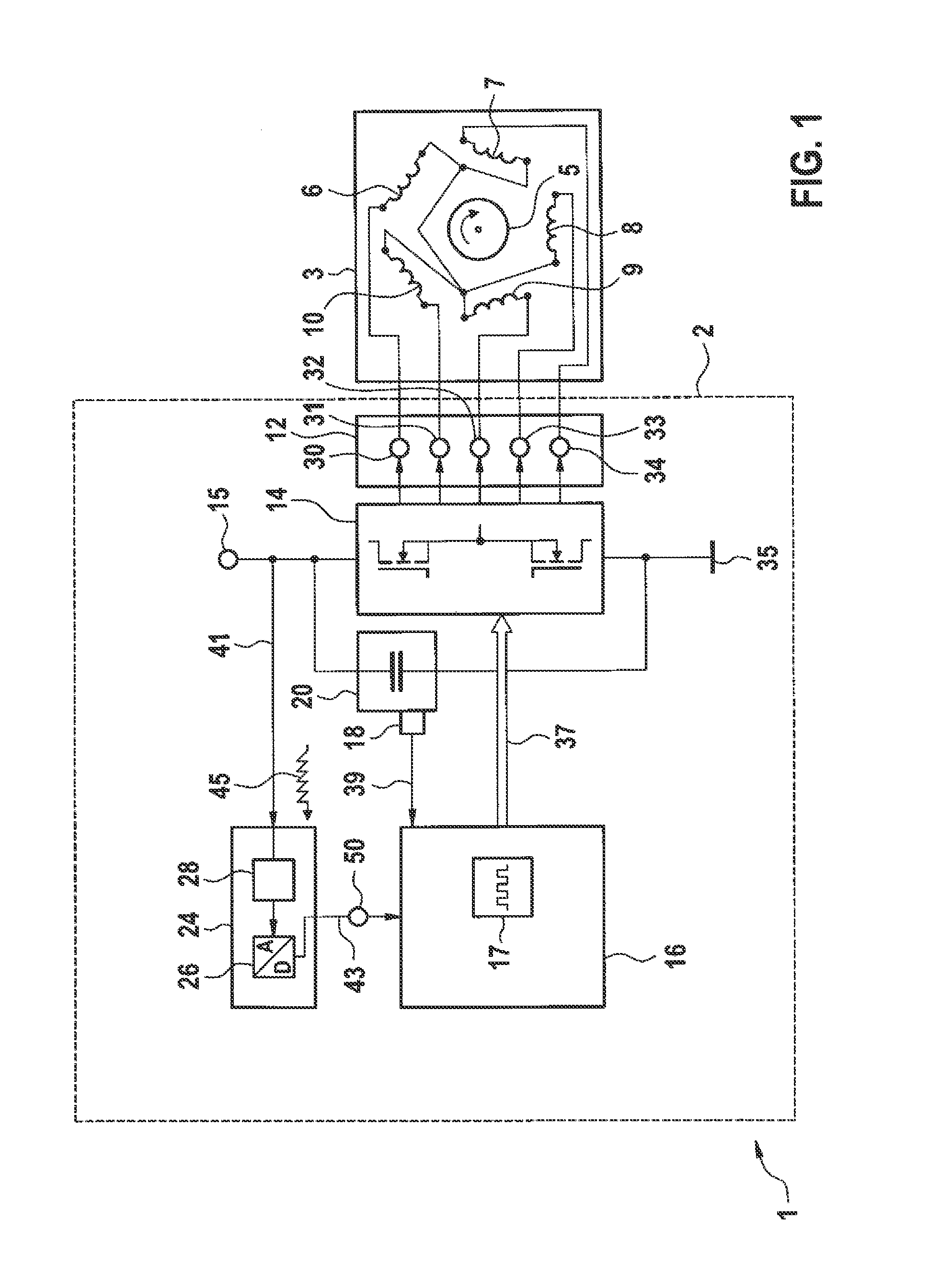
[0032]FIG. 1 shows—schematically—an exemplary embodiment for an electric machine 1. The electric machine 1 has a stator 3 and a rotor 5. In this exemplary embodiment, the stator 3 comprises five stator coils, namely the stator coils 6, 7, 8, 9 and 10. The stator coils of the stator 3 are connected to each other in a star connection in this exemplary embodiment. The stator coils of the stator 3 can also be interconnected with one another in another configuration, also in a pentagon circuit. The electric machine 1 also comprises a power output stage 14. The power output stage 14 is connected on the output side via an output 12 of a control unit 2 of the electric machine 1 to the stator 3 and there to the stator coils.

[0033]In this exemplary embodiment, the output 12 has a terminal for each stator coil of the stator 3. The output 12 has in this exemplary embodiment a terminal 30 for the stator coil 6, a terminal 31 for the stator coil 10 a terminal 32 for the stator coil 9, a terminal ...


PUM


Abstract

A control unit for an electric machine. The control unit has a processing unit and a power output stage connected to the processing unit. The power output stage is connected to outputs of the control unit for stator coils of a stator of the electric machine. The processing unit is designed to supply current to the power output stage for generating a stator field, in particular a rotating magnetic field. The control unit comprises an electrical energy store, in particular an intermediate circuit capacitor or accumulator, connected to the power output stage. The control unit includes an input for a control signal, for example a temperature signal. The processing unit is preferably designed to actuate the power output stage as a function of the temperature signal such that the energy store can be heated by a current application pattern generated by the power output stage. The current application pattern corresponds to a stator field which cannot generate an effective torque or a rotary motion, such as a full revolution of a rotor of the electric machine.

Description

BACKGROUND OF THE INVENTION[0001]The invention relates to a control unit for an electric machine. The control unit comprises a processing unit and a power output stage connected to the processing unit. The power output stage is connected to outputs of the control unit for stator coils of a stator of the electric machine. The processing unit is designed to supply current to the power output stage for generating a stator field, in particular a rotating magnetic field. The control unit comprises an electrical energy store connected to the power output stage, in particular an intermediate circuit capacitor or an accumulator.[0002]In motor vehicles, in particular electric or hybrid vehicles, an electric machine is supplied with current during engine operation by a control unit equipped with a power output stage; thus enabling the electric machine to produce a rotating magnetic field for rotating a rotor and therefore for driving the vehicle. At cold temperatures, for example at an ambien...

Claims


Application Information

Patent Timeline
Patent Type & Authority Applications(United States)
IPC IPC(8): G05F1/66
CPCG05F1/66H02M1/36H02M7/5387H02M7/5395H02M1/327
Inventor MAGINI, FABIOMEHRINGER, PAUL
Owner SEG AUTOMOTIVE GERMANY GMBH
Why Eureka
Try Eureka