Corporate aircraft engine upper placement and front swept wing duck type layout

A technology of engines and business jets, which is applied in the aviation field, can solve the problems of increasing the airflow velocity on the lower surface of the wing and reducing the lift of the wing, so as to achieve the effect of ensuring the control efficiency of the rudder surface, small wing area and long range

Inactive Publication Date: 2013-08-07
AVIC CHENGDU AIRCRAFT DESIGN & RES INST
View PDF7 Cites 13 Cited by
  • Summary
  • Abstract
  • Description
  • Claims
  • Application Information

AI Technical Summary

Problems solved by technology

[0006] 4. The engine is arranged on the lower surface of the wing. When the engine is working, the airflow velocity on the lower surface of the wing is increased, thereby reducing the lift of the wing.

Method used


Image

  • Corporate aircraft engine upper placement and front swept wing duck type layout
  • Corporate aircraft engine upper placement and front swept wing duck type layout
  • Corporate aircraft engine upper placement and front swept wing duck type layout

Examples


Embodiment Construction

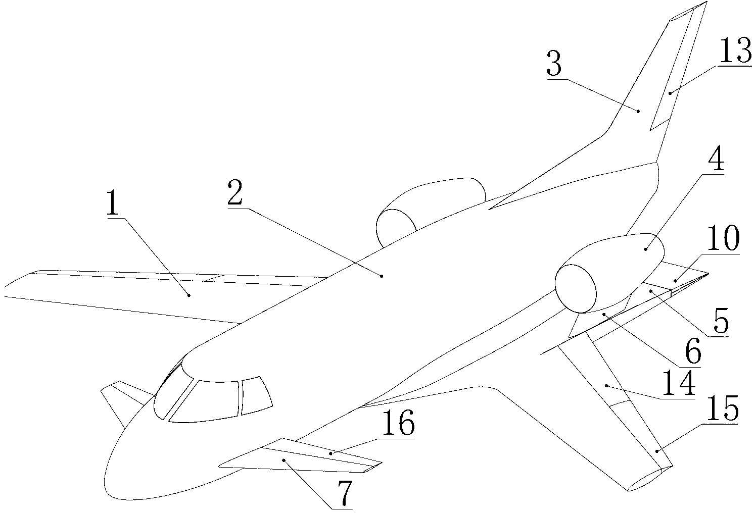
[0025] (1) The aircraft is mainly composed of fuselage 2, canard 7, wing 1, vertical tail 3, engine 4 and rear body strip 5, in which the engine 4 is supported on the rear body edge near the rear edge of the wing through the engine bracket 6 On the upper surface of the bar 5, an elevator 16 is arranged on the rear edge of the canard 7, an inner elevon 14 is arranged on the inner side of the rear edge of the wing, an outer elevon 15 is arranged on the outer side, and a side rudder 10 is arranged on the rear edge of the rear body side bar 5. , the rear edge of the vertical tail 3 is arranged with a rudder 13, see figure 1 ,

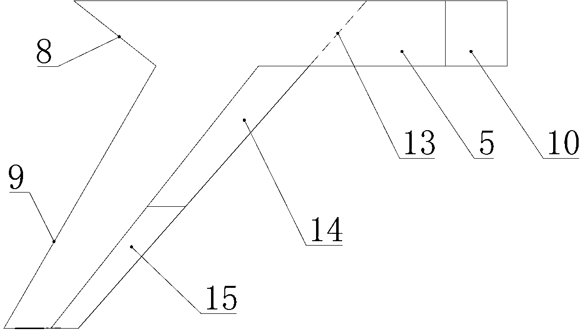
[0026] (2) The inner section 8 of the leading edge of the wing is swept back, the outer section 9 of the leading edge is swept forward, and the inner section 17 of the trailing edge of the wing is connected with the side strip 5 of the rear body, see figure 2 ;

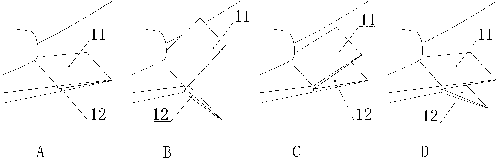
[0027] (3) The side bar rudder 10 at the rear edge of the rear body side bar 5 is a split de...


PUM


Abstract

The invention provides a corporate aircraft engine upper placement and front swept wing duck type layout, which belongs to the aviation field, and relates to a high lift drag ratio airplane total layout scheme. The airplane comprises a fuselage, duck wings, wings, a vertical fin, an engine and a rear body edge strip; the wing leading edge inner segment sweeps back; the wing leading edge outer segment sweeps forward, and the engine is supported on an upper surface of a rear body edge strip between a wing trailing edge and an edge strip rudder by an engine, and in the top view projection, an engine axis crosses the corner of the wing leading edge inner segment and the wing leading edge outer segment, and an elevator is arranged at the wing trailing edge, and an inner side elevating auxiliary wing is arranged at the inner side of the wing trailing edge inner side, and an outside elevating auxiliary wing is arranged at the outer side of the wing trailing edge; an edge strip rudder is arranged at the rear edge of the rear body edge strip, and a rudder is arranged at the rear edge of the vertical fin. The wing trailing edge inner segment is connected with a rear body edge strip; the edge strip rudder at the rear body edge strip trailing edge is in cracking type, and is composed of an upper rudder surface and a lower rudder surface, and the shapes of the fuselage and the wing are in smooth transition. The invention has the advantages of high rising and landing lift coefficient and high trim lift drag ratio, light structure weight, long endurance and long voyage.

Description

technical field [0001] The invention belongs to the field of aviation, and relates to a canard-style layout with an engine mounted on top and a forward-swept wing of a business jet, which is an overall layout plan for a high lift-to-drag ratio aircraft. Background technique [0002] Business jets generally adopt a conventional layout, and there are the following problems: [0003] 1. The wing is designed to be swept back. The outer washing airflow will make the wing surface gradually thicken from the wing root to the wingtip, causing separation at the wingtip. After the airflow is separated, the lift force is greatly reduced and causes a stall. After the wingtip stalls, It will expand from the wingtip to the center of the wing, and the stall area will become larger and larger, which may greatly reduce the aileron control efficiency, or even reverse the effect, affecting the control stability; [0004] 2. In order to balance the lift moment of the wing and ensure the aircraf...

Claims


Application Information

Patent Timeline
Patent Type & Authority Applications(China)
IPC IPC(8): B64C3/32B64C3/36
CPCB64C3/32
Inventor 沈君彦邓章春朱楠周迎春潘剑武李荣强
Owner AVIC CHENGDU AIRCRAFT DESIGN & RES INST
Why Eureka
Try Eureka