Row cycle real-time adjustment system and method for large-view-field space camera

A technology of space camera and real-time adjustment, applied in the direction of photographic devices, etc., can solve problems such as difficulty in guaranteeing real-time performance, inconsistency of the real situation, and failure to consider the flattening of the earth

Active Publication Date: 2013-08-14
CHANGCHUN INST OF OPTICS FINE MECHANICS & PHYSICS CHINESE ACAD OF SCI
View PDF4 Cites 6 Cited by
  • Summary
  • Abstract
  • Description
  • Claims
  • Application Information

AI Technical Summary

Problems solved by technology

[0009] The present invention solves the problems that existing methods are only applicable to space cameras with a small field of view, d

Method used


Image

  • Row cycle real-time adjustment system and method for large-view-field space camera
  • Row cycle real-time adjustment system and method for large-view-field space camera
  • Row cycle real-time adjustment system and method for large-view-field space camera

Examples


specific Embodiment approach 1

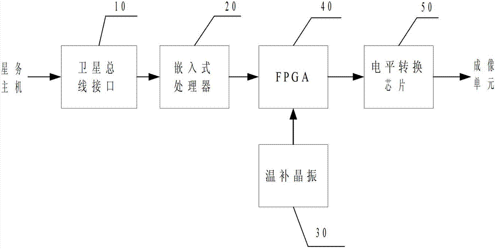
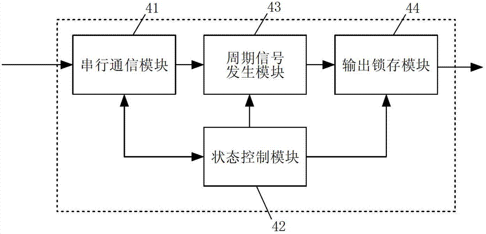
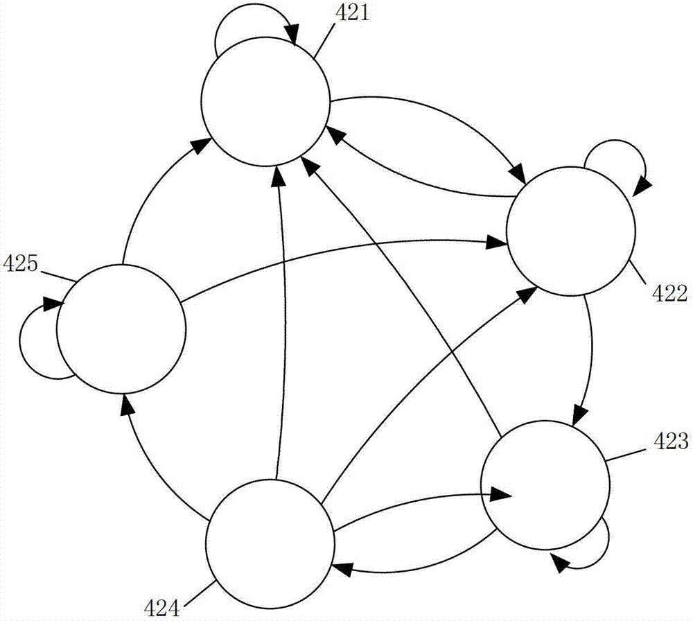
[0062] Specific implementation mode 1. Combination Figure 1 to Figure 4 Describe this embodiment mode, the real-time adjustment system of the line cycle of a large field of view space camera, including a satellite bus interface 10, an embedded processor 20, a temperature-compensated crystal oscillator 30, an FPGA 40 and a level conversion chip 50;

[0063] Satellite bus interface 10: It is composed of a bus protocol chip and a bus level conversion chip, and sends the data and instructions sent by the star host through the satellite bus to the embedded processor.

[0064] Embedded processor: receive data and instructions transmitted from the satellite bus interface 10; calculate each imaging in real time according to parameters such as the current position and speed of the satellite in the data, and the half field angle corresponding to the effective pixel center position of each imaging unit The line cycle code value corresponding to the unit. And the received imaging unit s...

specific Embodiment approach 2

[0084] Specific embodiment two, combine Figure 5 to Figure 7 Describe this embodiment, the method for adjusting the line period of a large field of view space camera in real time; in this embodiment, assume that the current position of the satellite in the equatorial inertial coordinate system (X ECI ,Y ECI ,Z ECI ) and speed (VX ECI ,VY ECI ,VZ ECI ) are (-3080067.9, 2051763.6, -5974793.5) (unit: m) and (6241.45, -1768.87, -3824.97) (unit: m / s), respectively.

[0085] In step 110 , the embedded processor 20 receives data and instructions from the satellite bus interface 10 , and then proceeds to step 120 .

[0086] In step 120 , if the received imaging unit startup command or imaging unit shutdown command is received, go to step 130 , otherwise go to step 140 .

[0087] In step 130 , the imaging unit power-on command or the imaging unit power-off command is forwarded to FPGA 40 to control the enabling and disabling of the line cycle signal output, and then return to st...


PUM


Abstract

The invention discloses a row cycle real-time adjustment system and a row cycle real-time adjustment method for a large-view-field space camera, is based on an ellipsoidal model of the earth, considers the image motion velocity differences at different view field positions of the large-view-field space camera, and solves the problems that the existing method is only suitable for small-view-field space cameras, does not consider the compression of the earth, is inconsistent with the true condition and has difficulty in guaranteeing the instantaneity, and the like. The row cycle real-time adjustment system of the large-view-field space camera is composed of a satellite bus interface, an embedded processor, a temperature-compensation crystal oscillator, an FPGA (field programmable gate array) and a level switch chip, wherein the FPGA is used for finishing generation and output enable control of multiple paths of row cycle signals. Compared with the traditional method, the method provided by the invention can effectively reduce the volume, the power consumption of large-view-field space camera controllers, and the machine-hour occupation of embedded processors.

Description

technical field [0001] The invention relates to a large-field-of-view space camera for observing the earth on a remote sensing satellite platform, in particular to a method and a system for real-time adjustment of the travel cycle of the large-field-of-view space camera during on-orbit photography. Background technique [0002] When the space camera is photographing the earth, under the combined effect of the earth's rotation motion and the satellite's orbital motion, the relative motion of the camera and the object points will cause image motion, resulting in a decrease in imaging quality. At present, transmission-type remote sensing satellites mainly eliminate the degradation of imaging quality caused by image motion by adjusting the line transfer cycle (referred to as line cycle) of the space camera imaging sensor to match the size of the image motion speed. The line period represents the transfer frequency of the charge packets generated by the imaging sensor through pho...

Claims


Application Information

Patent Timeline
IPC IPC(8): G01C11/02
Inventor 武星星刘金国周怀得余达
Owner CHANGCHUN INST OF OPTICS FINE MECHANICS & PHYSICS CHINESE ACAD OF SCI
Why Eureka
Try Eureka