Power tool

A technology for working tools and tools, applied in the direction of manufacturing tools, wood processing appliances, metal processing, etc., can solve problems such as inability to use and increase the cost of bearing manufacturing

Inactive Publication Date: 2013-08-21
MAKITA CORP
View PDF6 Cites 1 Cited by
  • Summary
  • Abstract
  • Description
  • Claims
  • Application Information

AI Technical Summary

Problems solved by technology

However, since the outer surface of the bearing is formed into a curved shape in cross-section, an existing (off-the-shelf) cylindrical bearing cannot be used, which will increase the manufacturing cost of the bearing. From this point of view, there are room for improvement

Method used


Image

  • Power tool
  • Power tool
  • Power tool

Examples


no. 1 Embodiment approach )

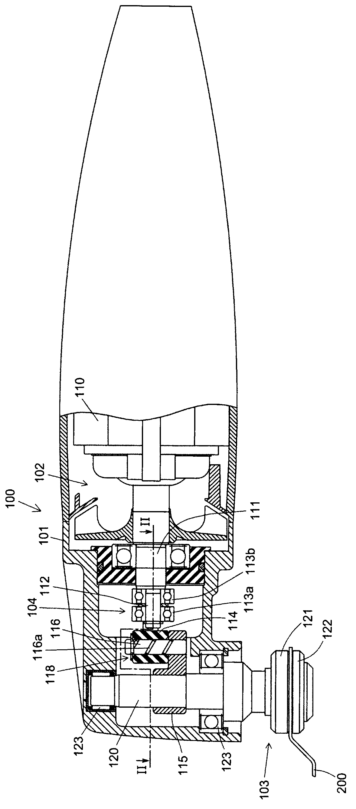
[0030] Refer below Figure 1~Figure 3 The first embodiment of the present invention will be described in detail. In this embodiment, the working tool of the present invention will be described by taking an electric vibration tool as an example.

[0031] Such as figure 1 As shown, the electric vibration tool 100 is a work tool that can perform processing operations such as cutting and grinding on a workpiece according to the type of processing tool (working part) installed, and a blade or grinding blade can be selectively installed on it. Various processing tools such as pads can vibrate (slightly oscillate) the installed processing tools to perform processing operations. In this embodiment, the blade 200 will be described as an example of a machining tool. In addition, processing tools such as the blade 200 have an embodiment structure corresponding to the "tip tool" in the present invention.

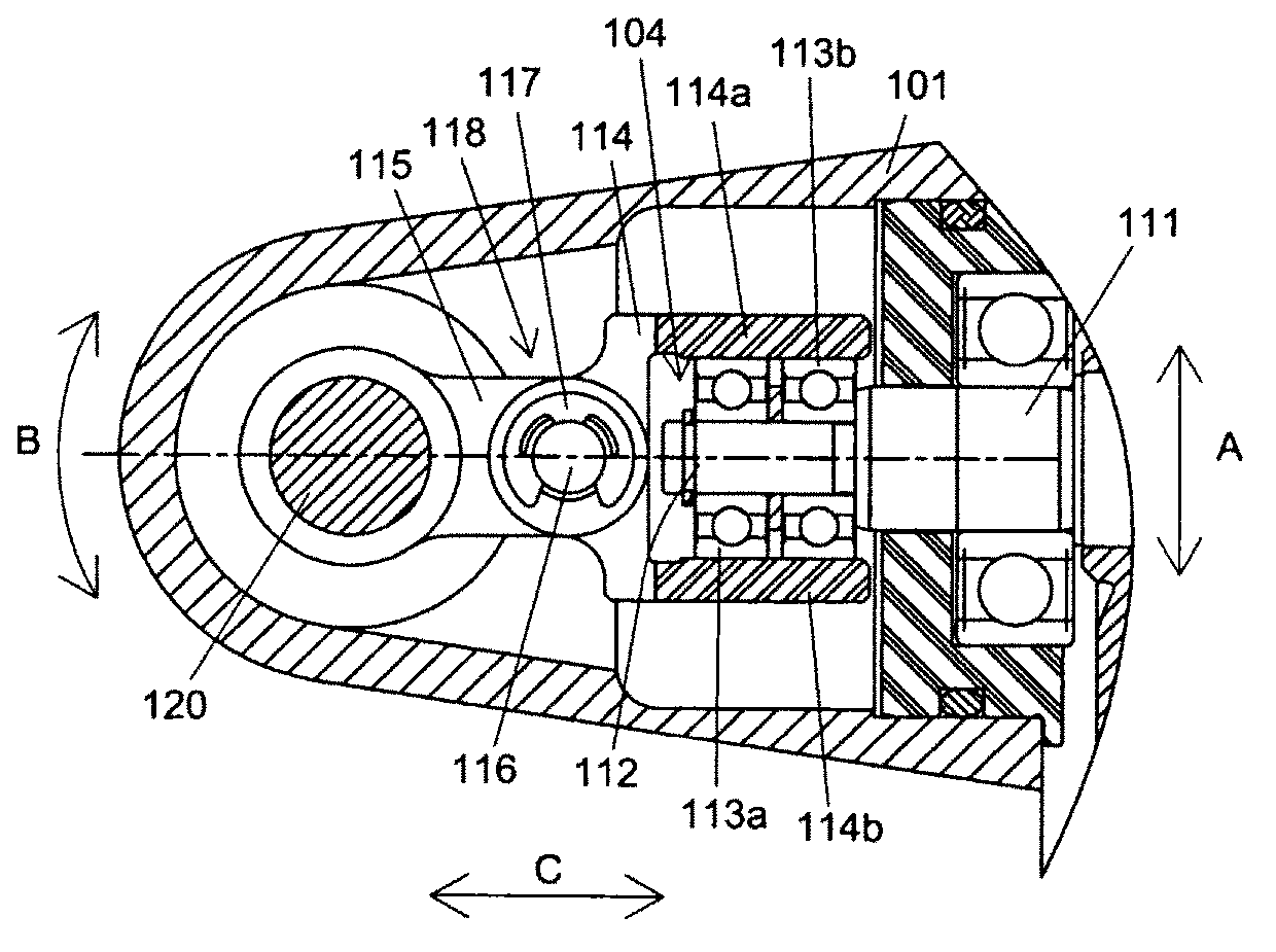
[0032] Such as figure 1 , figure 2 As shown, the electric vibration tool 100...

no. 2 Embodiment approach )

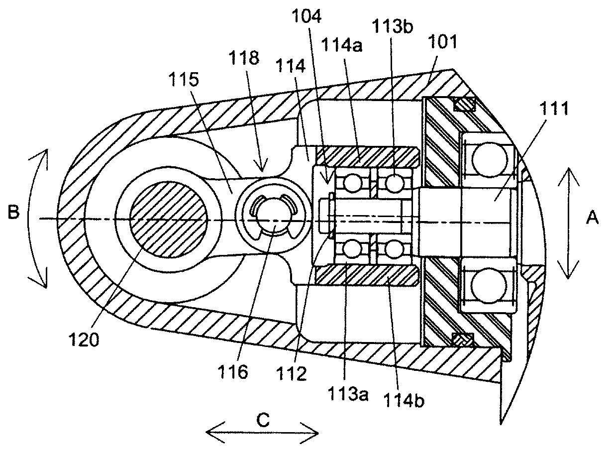
[0048] Refer below Figure 4~Figure 6 A second embodiment of the present invention will be described in detail. Compared with the first embodiment, the second embodiment is different in the structure related to the driven arm, the main shaft connection arm, and the bearing, and the other structural elements are the same as those of the first embodiment.

[0049] Such as Figure 4 As shown, in the second embodiment, only one bearing 213 is provided. Additionally, if Figure 5 , Figure 6 As shown, the follower arm 214 has a first arm portion 214 a and a second arm portion 214 b, and is disposed outside the bearing 213 so as to be able to contact the bearing 213 . In the direction from the side of the eccentric moving part 104 constituted by the eccentric shaft 112 and the bearing 213 to the side of the main shaft 120 ( Figure 5 In the C direction), the connecting part for connecting the driven arm 214 and the main shaft connecting arm 215 is arranged in parallel with the ...


PUM


Abstract

An electric oscillating tool (100) which actuates a tool (200) around a spindle (120) is provided. The electric oscillating tool (10) comprises a motor (110), the spindle (120) which is driven by the motor (110), and a driving transmission member which transmits a rotational output of the motor (110) to the spindle (120). The driving transmission member includes an eccentric moving member, a driven arm (114), a spindle connecting arm (115), and a pin (116) which connects the driven arm (114) and the spindle connecting arm (115) in a relatively rotatable manner. The eccentric moving member comprises an eccentric shaft (112) which moves eccentrically around a rotational shaft of the motor (110), a first bearing (113a), and a second bearing (113b).

Description

technical field [0001] The present invention relates to a work tool for driving a clamped tip tool to perform work. Background technique [0002] Japanese Patent Laid-Open Publication No. 2011-230204 discloses a work tool having a drive shaft on which a tip tool is clamped and fixed, and the tip tool is driven to perform work. In addition, in this power tool, a rocker arm is mounted on the drive shaft. The rocker arm has a bifurcated engaging portion, and an eccentric shaft is provided on the top end (head end) of the output shaft of the motor. There is a bearing, and the bifurcated engaging portion of the rocker arm engages with the bearing from the outside of the bearing. The engaging part and the eccentric shaft rotate and move around the output shaft of the motor, and the rocker arm rotates and moves back and forth around the drive shaft. Accordingly, the drive shaft performs reciprocating rotational movement, causing the tip tool to oscillate around the axis of the dr...

Claims


Application Information

Patent Timeline
Patent Type & Authority Applications(China)
IPC IPC(8): B24B45/00B24B23/04
CPCB24B23/04A61B17/14B23Q5/00B23D51/00B27B19/006B25F5/00B25F5/001B27B19/00A61B17/142
Inventor 生田洋规
Owner MAKITA CORP
Why Eureka
Try Eureka