
Piezoelectrically-driven inchworm-type positioning workbench based on flexible amplification principle
A technology of piezoelectric drive and workbench, which is applied to the parts of the instrument, instruments, etc., can solve the problem of low movement speed and achieve the effect of large bearing capacity, increased movement speed and large stroke
- Summary
- Abstract
- Description
- Claims
- Application Information
AI Technical Summary
Problems solved by technology
Method used
Image

Examples
Embodiment 1
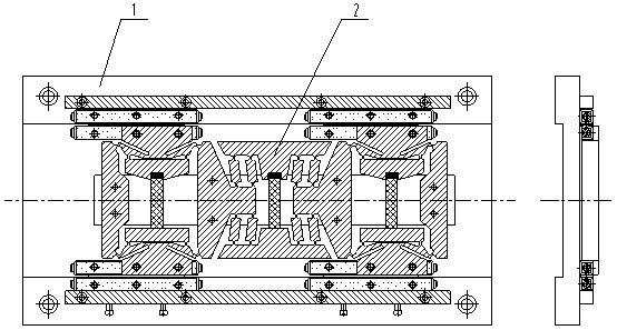
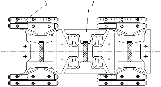
[0021] see Figure 1~Figure 8 , the piezoelectric-driven inchworm-type positioning workbench based on the principle of flexible amplification includes a guide adjustment mechanism 1 and an inchworm-type motion platform 2, and is characterized in that: the inner side of the inchworm-type motion platform 2 is connected to the guide adjustment mechanism 1, and the inchworm-type The timing control of the piezoelectric ceramics in the motion platform 2 enables the inchworm-type motion platform 2 to walk and position in a straight line along the guide adjustment mechanism 1 .
Embodiment 2
[0023] This embodiment is basically the same as Embodiment 1, and the special features are as follows:
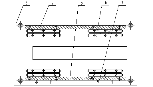
[0024] The guide adjustment mechanism 1 includes a base 3, a reference baffle 4, an adjustment baffle 5, two pairs of cross roller guide rails 6 and 4 adjustment screws 7; the reference baffle 4 and the adjustment baffle 5 The upper and lower sides of the base 3 are respectively fixed by screws, and the outer guide rails of the upper half of the two pairs of cross roller guide rails 6 are fixed on the base 3 in close contact with the inside of the reference baffle 4 as a reference. The outer guide rail of the lower half of the cross roller guide 6 is connected with the base 3 by screws, and the screws cannot be tightened, so that the posture and posture of the outer guide rail of the lower half of the cross roller guide 6 can be adjusted; two pairs of cross roller guides The inner guide rail of the guide rail 6 is fixedly connected with the inchworm-type motion platform 2; ...
Embodiment 3
[0030] refer to figure 1 , a piezoelectric-driven inchworm-type positioning worktable based on the principle of flexible amplification, which is composed of a guide adjustment mechanism 1 and an inchworm-type motion platform 2 . The inchworm type motion platform 2 is connected with the inner side of the guide adjustment mechanism 1 through screws.
[0031] refer to figure 2 , The above-mentioned guide adjustment mechanism 1: consists of a base 3, a reference baffle 4, an adjustment baffle 5, two pairs of cross roller guide rails 6 and 4 adjustment screws 7. The reference baffle 4 and the adjustment baffle 5 are respectively fixed on the upper and lower sides of the base 3, and the outer guide rails of the upper half of the two pairs of cross roller guides 6 are fixed on the inside of the reference baffle 4 as a reference. On the base 3, the outer guide rails of the lower half of the two pairs of cross roller guide rails 6 are connected to the base 3 through screws, and the ...
PUM
 Abstract
Description
Claims
Application Information