A magnetic wire tooling

A technology of electric wires and tooling, which is applied in the field of electrical accessories connection devices, and can solve problems such as inconvenient disassembly and assembly, and easy slipping of power supply terminals

Active Publication Date: 2016-05-04
FUJIAN QIANGLI PHOTOELECTRICITY
View PDF5 Cites 0 Cited by
  • Summary
  • Abstract
  • Description
  • Claims
  • Application Information

AI Technical Summary

Problems solved by technology

[0003] Aiming at the defects existing in the prior art, the present invention provides a magnetic wire tooling, which can solve the problem that the crocodile clip is connected to the screw-type power supply terminal, which is easy to slip and is inconvenient to disassemble.

Method used


Image

  • A magnetic wire tooling
  • A magnetic wire tooling
  • A magnetic wire tooling

Examples


Embodiment Construction

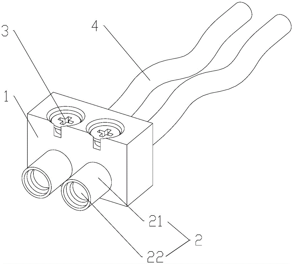
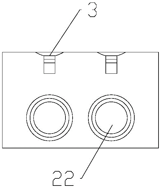
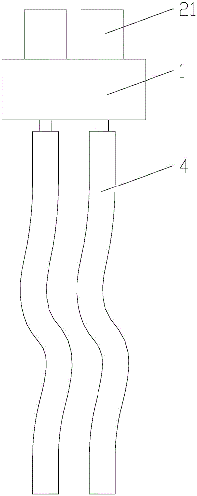
[0019] Such as Figure 1 to Figure 6 As shown in any one, a magnetic wire tooling is composed of an insulating base body 1, a metal conductive connector 2, a wire fixing screw 3 and a wire 4; the metal conductive connector 2 is composed of a conductive metal shell 21 and a cylindrical magnet 22 The cylindrical magnet 22 is embedded in the conductive metal shell 21, and the conductive metal shell 21 is inserted in the insulating seat body 1; the upper surface of the metal conductive connector 2 has an incoming wire hole 23, and the wire 4 is inserted into the incoming wire In the hole 23 ; the side of the metal conductive connector 2 has a screw hole 24 , and the screw hole 24 cooperates with the wire fixing screw 3 to fix the wire 4 inserted into the wire inlet hole 23 .

[0020] The two wires 4 are respectively inserted into the two corresponding wire inlet holes 23 , and then fastened with the wire fixing screws 3 in the side screw holes 24 of the metal conductive connector ...


PUM


Abstract

The invention discloses a magnetic electric wire tool, and belongs to the field of electrical auxiliary connecting devices. The magnetic electric wire tool comprises a bench insulator body, metallic-conduction connecting pieces, guide line fastening screws and guide lines. Each metallic-conduction connecting piece comprises a metallic-conduction outer shell and a cylindrical magnet, the cylindrical magnets are inlaid inside the metallic-conduction outer shells, and the metallic-conduction outer shells are inserted into the bench insulator body. Entrance holes are formed in the surfaces of the upper portions of the metallic-conduction connecting pieces, and the guide lines are inserted into the entrance holes. Screw holes are formed in the side faces of the metallic-conduction connecting pieces, and the screw holes are matched with the guide line fastening screws to enable the guide lines to be fixed. In the using process, the tool is connected to a screw type power binding post of a device to be measured through magnetism, and thus the problems that slipping can occur easily and dismounting and mounting are inconvenient when an alligator clip is connected to the screw type power binding post are solved.

Description

technical field [0001] The invention relates to a connecting device for electrical accessories, in particular to a magnetic wire tooling. Background technique [0002] In the manufacturing process of the LED display module, when it is necessary to power on the LED module for testing, it is necessary to connect the power cord on the test equipment to the power terminal of the LED module, and the power wiring on the LED module The column is two screws. In the prior art, the screws are clamped by two crocodile clips. The utility model patent with the authorized notification number CN201466256U discloses such a crocodile clip. Using the technical solution of the crocodile clip, the crocodile clip is easy to It slipped off from the screw-type terminal, and because it needs to be connected and disassembled repeatedly during the test, it is not convenient to connect and disassemble, so this case arises. Contents of the invention [0003] Aiming at the defects existing in the pri...

Claims


Application Information

Patent Timeline
Patent Type & Authority Patents(China)
IPC IPC(8): H01R11/30
Inventor 李明黄加园张余涛
Owner FUJIAN QIANGLI PHOTOELECTRICITY
Why Eureka
Try Eureka