Bi-directional aerating high pressure inflator

A hand-pulled and inflated technology, applied in liquid variable volume machinery, variable displacement pump components, machines/engines, etc., can solve problems such as laboriousness, limiting piston design space, and affecting the inflation efficiency of hand-pulled gas cylinders.

Active Publication Date: 2013-10-23
NINGBO BRAVO MFG OF INFLATORS & ACCESSORIES
View PDF10 Cites 8 Cited by
  • Summary
  • Abstract
  • Description
  • Claims
  • Application Information

AI Technical Summary

Problems solved by technology

[0006] The defect of this pressure relief valve structure is that the valve stem is held by the spring to keep the tendency of closing the valve port. When the handle is pressed down, the pressure relief valve will be in the closed state again. When pulling up the handle, the pressure of the upper air chamber must reach the set opening pressure of the pressure relief valve (that is, the pre-tightening pressure provided by the spring) before the pressure relief valve opens. still more laborious
[0007] There is also the existing two-way inflatable hand pump, the breathing valve set on the piston is based on inertia thinking, and the designer will use the circular breathing valve without thinking. This is a common practice, because it is a high pressure hand pump. Pulling the air cylinder, so the cross section of the cylinder body is required to be small, and the entire cylinder body is relatively small, which limits the design space of the piston. It is necessary to install a circular valve port with a breathing valve on the piston, and the diameter of the valve port is very large. Due to the limitation, the diameter of the valve port on the piston is small, and the air flow is also small, which greatly affects the inflation efficiency of the hand pump

Method used


Image

  • Bi-directional aerating high pressure inflator
  • Bi-directional aerating high pressure inflator
  • Bi-directional aerating high pressure inflator

Examples


Embodiment Construction

[0034] The present invention will be further described in detail below in conjunction with the accompanying drawings and embodiments.

[0035] like Figure 1-12 Shown is the first embodiment of the present invention.

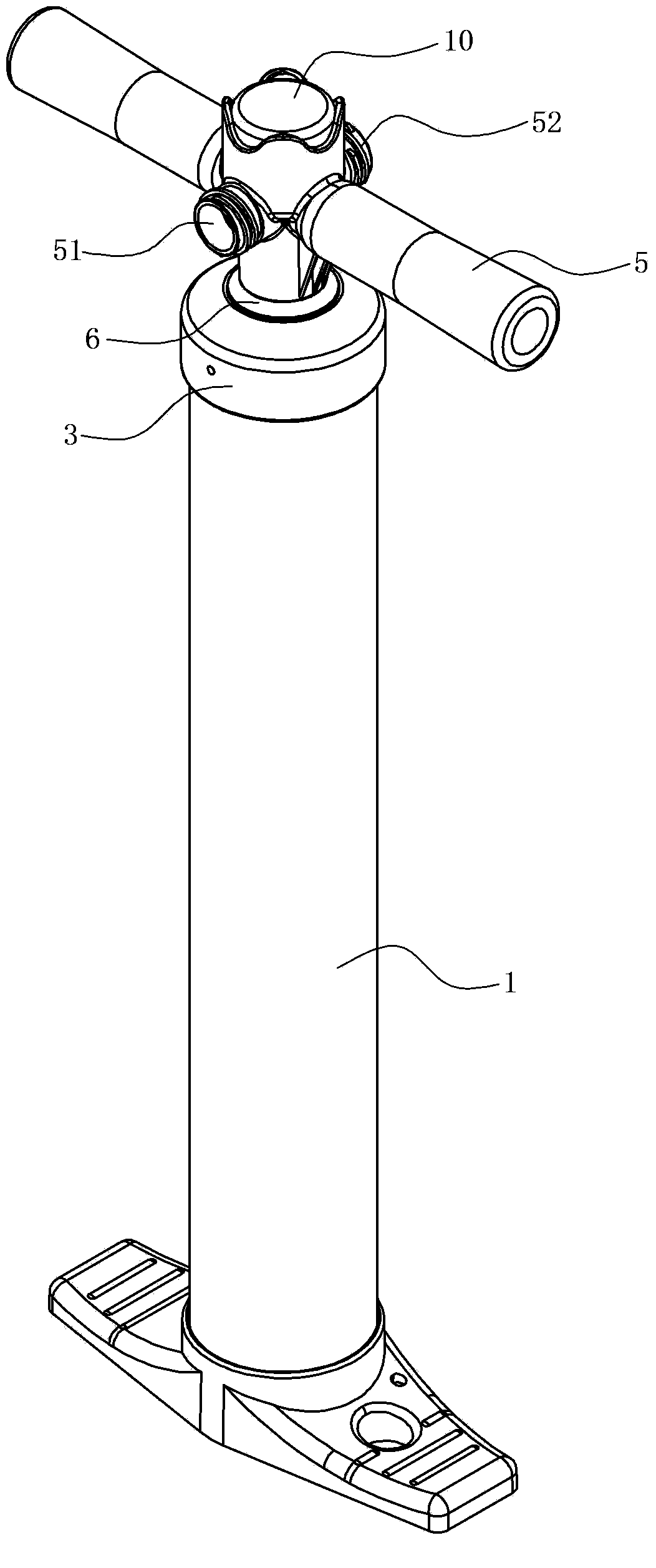
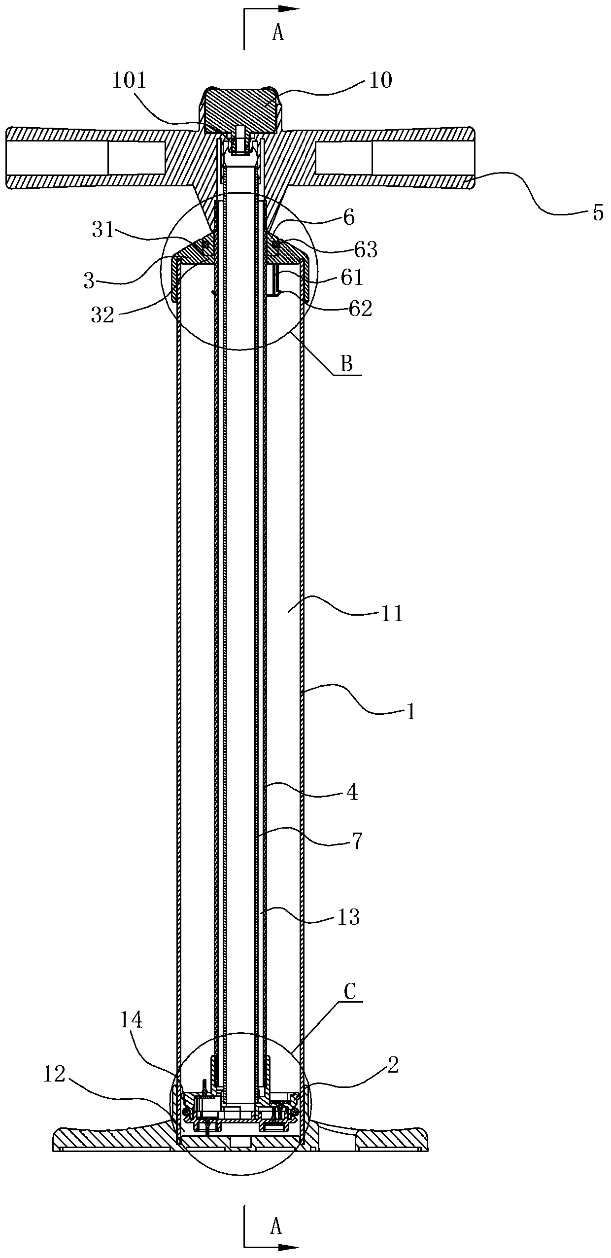
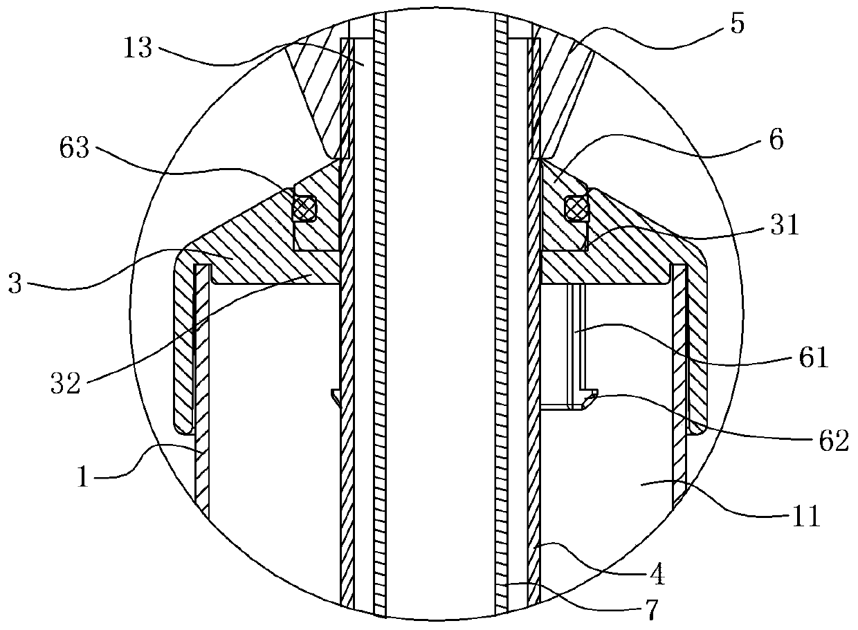
[0036] A two-way inflatable high-pressure hand pump, comprising a cylinder body 1, a piston 2 is arranged inside the cylinder body, the piston 2 divides the inner space of the cylinder body into an upper air chamber 11 and a lower air chamber 12, and an upper air chamber 12 is arranged on the upper part of the cylinder body 1 The cover 3 and the center of the upper cover 3 are provided with a linkage pipe 4 , the upper end of the linkage pipe 4 is connected with a handle 5 , and the lower end of the linkage pipe 4 is connected with the piston 2 .

[0037] A piston ring 14 is embedded on the outer periphery of the piston 2, and the piston ring 14 is an O-ring. like Figure 10-12 As shown, the interior of the piston 2 is provided with an independent air intake ...


PUM


Abstract

The invention relates to a bi-directional aerating high pressure inflator, which comprises an inflator body and a piston, wherein the piston divides an internal space of the inflator body into an upper air chamber and a lower air chamber; and an upper cover is arranged on an upper part of the inflator body. The bi-directional aerating high pressure inflator is characterized in that a valve hole communicated with the upper air chamber and outside is formed in the upper cover; a plurality of fillets arranged at intervals along the circumference are formed on an inner hole wall of the valve hole along a radial direction; a valve cover capable of sliding up and down is arranged in the valve hole; a plurality of downwards extending guiding bars arranged at intervals along the circumference are arranged under the valve cover; and a hook part tapped with an inner top wall of the upper cover is arranged on the outer sides of the bottom parts of the guiding bars. When pressure generated by air pressure of the upper air chamber on a valve cover is larger than frictional force between the valve cover and an inner wall of the valve hole, the valve cover is pushed to move upwards, the valve hole is at an open state, a grip is pulled upwards in a labor saving manner, without a support force of a spring, the valve cover is at a loosening state, the grip is pulled upwards again, the valve cover can be opened easily, the inflator is changed to be in a one-way inflating mode, and when the inflator is inflated to be with a certain pressure by inflating equipment, the way that the grip is pulled upwards is still labor-saving.

Description

technical field [0001] The invention relates to a high-pressure hand pump that can be operated by the user and can continue to inflate or pump air when the handle is pushed or pulled. Background technique [0002] At present, there are quite a lot of types of hand pumps (also called air pumps). The traditional pump includes a cylindrical body, and a piston operated by a connecting rod is assembled in the body. A grip for the user to hold is provided at the top of the connecting rod, and an inflatable tube extends from the lower end of the main body. When the user pulls up the handle, air will enter under the piston inside the body, and when the user presses down the handle, the piston will push the air in the body into the inflatable tube to provide an inflation. This kind of traditional hand-held air cylinder is a one-way hand-held air cylinder, that is, when the piston moves up and down in a round-trip stroke, only a single stroke can provide inflation, and the use effici...

Claims


Application Information

Patent Timeline
Patent Type & Authority Applications(China)
IPC IPC(8): F04B33/00F04B39/00
Inventor 艾玛诺.维多利奥.梅迪契
Owner NINGBO BRAVO MFG OF INFLATORS & ACCESSORIES
Why Eureka
Try Eureka