Cloth rolling equipment

A kind of equipment and cloth rolling technology, which is applied in the field of cloth manufacturing, can solve the problems that affect the efficiency of cloth rolling, the rolling of the paper tube and the rotating shaft, and the difficulty of pressing and fitting the rotating shaft and the paper tube.

Inactive Publication Date: 2018-06-29
HANGZHOU LESHOU TECH CO LTD
View PDF0 Cites 0 Cited by
  • Summary
  • Abstract
  • Description
  • Claims
  • Application Information

AI Technical Summary

Problems solved by technology

[0002] In the fabric manufacturing process, the last process is to roll the fabric. Most of the existing fabric rolling devices use a paper tube sleeved on the rotating shaft to wind the cloth on the paper tube, and then pull the rotating shaft out of the paper tube. Pull out; but in this method, it is difficult to press and fit the rotating shaft and the paper tube tightly, because the rotating shaft is not easy to pull out from the paper tube after pressing, but if it is too loose, it will easily cause the paper tube and the rotating shaft to roll relative to each other, which will affect the efficiency of cloth rolling

Method used


Image

  • Cloth rolling equipment
  • Cloth rolling equipment
  • Cloth rolling equipment

Examples


Embodiment Construction

[0019] In order to enable those skilled in the art to better understand the solutions of the present invention, the technical solutions in the embodiments of the present invention will be clearly and completely described below in conjunction with the drawings in the embodiments of the present invention.

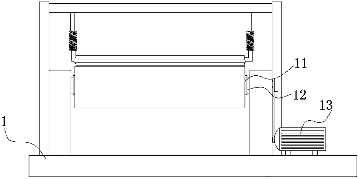
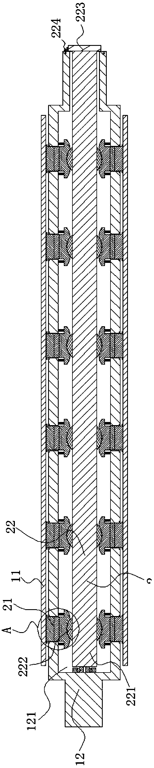
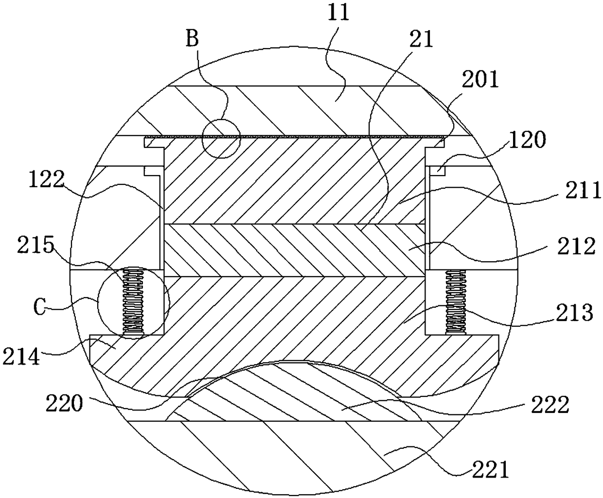
[0020] Such as Figure 1-5 As shown, a cloth rolling device includes a frame body 1, a cloth rolling drum 11, a rotating part 12, a placement cavity 121 and a driving part 13; the frame body 1 is a metal frame, and the driving part 13 is a motor. The cloth rolling drum 11 is an existing paper drum in the market, so it will not be repeated here; the rotating member 12 is a metal tube with a hollow inside, and the cavity formed by the hollow inner wall of the rotating member 12 is the The above-mentioned placement chamber 121; the rotating member 12 is provided with a plurality of movable openings 122 arranged at intervals, and the described movable openings 122 communicate wit...


PUM


Abstract

The invention discloses cloth rolling equipment. The cloth rolling equipment comprises a frame body, a cloth winding barrel, a rotating part, a placing cavity and a driving part, wherein the rotatingpart is arranged in the cloth winding barrel in a penetrating mode, the placing cavity is arranged on the rotating part, and the driving part is used for driving the rotating part to rotate; a pressing mechanism for synchronously rotating the cloth winding barrel and the rotating part is arranged on the rotating part, and the pressing mechanism comprises a pressing component and a pushing component, wherein the pressing component is in rotation fit with the inner wall of the cloth winding barrel, and the pushing component is matched with the pressing component; and the pushing component is arranged in the placing cavity. Friction force is generated between the pressing part and the inner wall of the cloth winding barrel, the cloth winding barrel and the rotating part are kept relatively static, and the rotating part can drive the cloth coiling barrel to rotate synchronously, so that the cloth winding barrel is prevented from rotating relative to the rotating part; and a pushing component is arranged to push a pressing component to move, so that the pressure of the pressing component on the cloth winding barrel is improved, and the friction force between the cloth winding barrel andthe pressing component is improved.

Description

technical field [0001] The invention belongs to the technical field of cloth manufacturing, and in particular relates to a cloth rolling device. Background technique [0002] In the fabric manufacturing process, the last process is to roll the fabric. Most of the existing fabric rolling devices use a paper tube sleeved on the rotating shaft to wind the cloth on the paper tube, and then pull the rotating shaft out of the paper tube. Pull out; but in this method, it is difficult to tightly press and fit the rotating shaft and the paper tube, because the rotating shaft is not easy to pull out from the paper tube after compression, but if it is too loose, it will easily cause the paper tube and the rotating shaft to roll relative to each other, affecting the efficiency of cloth rolling . Contents of the invention [0003] In order to overcome the deficiencies of the prior art, the present invention provides a cloth rolling device capable of compressing a paper roll. [0004]...

Claims


Application Information

Patent Timeline
Patent Type & Authority Applications(China)
IPC IPC(8): B65H18/10B65H23/16
CPCB65H18/10B65H23/16B65H2701/174B65H2701/19
Inventor 李颖
Owner HANGZHOU LESHOU TECH CO LTD
Why Eureka
Try Eureka