Injection device of injection molding machine and its operation method

An operation method and injection molding machine technology, applied in the field of injection molding machines, can solve the problems of large size, large investment, high energy consumption, etc., and achieve the effect of large capacity

Active Publication Date: 2016-06-08
广东联升精密智能装备科技有限公司
View PDF6 Cites 0 Cited by
  • Summary
  • Abstract
  • Description
  • Claims
  • Application Information

AI Technical Summary

Problems solved by technology

For the molding method of large plastic products, if the traditional injection molding process is used to complete, the investment in equipment and molds is very high, and the investment cost of tens of millions will also increase the production cost of large plastic products, which is not conducive to promotion
For example, some large-scale plastic pipe fittings, plastic trays, automobile plastic covering parts, plastic municipal pits, etc., the product volume requires an injection volume of more than 15 kg. If such a large injection volume is produced by a traditional injection molding machine, it will take about 2000. Tons of injection molding machines to complete, so the equipment is bulky, high energy consumption, large investment

Method used


Image

  • Injection device of injection molding machine and its operation method

Examples


Embodiment Construction

[0034] The present invention will be further described below in conjunction with the accompanying drawings and embodiments.

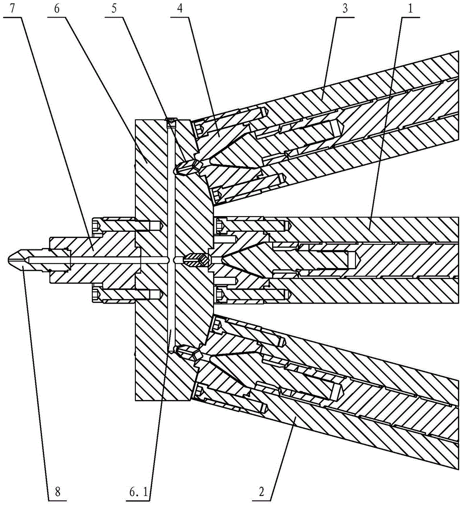
[0035] see figure 1 , The injection device of the injection molding machine includes injection mechanisms, and there are more than three injection mechanisms, and each injection mechanism is connected to the hot runner plate 6 through its front end flange 4 .

[0036] In this embodiment, a nozzle flange 7 is arranged on the hot runner plate 6 , and the nozzle 8 is arranged on the nozzle flange 7 .

[0037] The nozzle 8 is threadedly connected with the nozzle flange 7 . The nozzle is in direct contact with the mold. The nozzle flange is installed in the middle of the hot runner plate.

[0038] The hot runner plate 6 is provided with a melt passage 6.1 connecting the injection mechanism and the nozzle 8, and a check valve 5 is provided between each injection mechanism and the melt passage 6.1. In other words, a check valve 5 is provided between the in...


PUM


Abstract

The invention relates to an ejection device of an injection molding machine and an operation method of the ejection device. The ejection device of the injection molding machine comprises more than three ejection mechanisms. All the ejection mechanisms are connected with a hot runner manifold through flanges at the front ends of the ejection mechanisms. The hot runner manifold is provided with an ejection nozzle flange, and an ejection nozzle is arranged on the ejection nozzle flange. The ejection nozzle is connected with the ejection nozzle flange through threads. The hot runner manifold is provided with melt channels communicating the ejection mechanisms and the ejection nozzle. Check valves are arranged between all the ejection mechanisms and the melt channels. The ejection mechanisms include the first injection mechanism, the second ejection mechanism and the third ejection mechanism, and the first injection mechanism, the second ejection mechanism and the third ejection mechanism are arranged in the shape of a sector. The ejection device of the injection molding machine has high capacity and can perform multiple times of injection according to the weight of a plastic product, therefore, the injection amount is very large, and the number of optimum injection times can be determined according to the product and the mold technology in the actual using process. The ejection device of the injection molding machine has the advantages of being flexible to operate, high in injection efficiency, high in capacity, wide in application range and the like.

Description

technical field [0001] The invention relates to an injection molding machine, in particular to an injection device of the injection molding machine and an operating method thereof. Background technique [0002] With the rapid development of industry and urbanization, the use of large plastic products has become very common. For the molding method of large plastic products, if the traditional injection molding process is used to complete it, the investment in equipment and molds is very high, and the investment cost of tens of millions will also increase the production cost of large plastic products, which is not conducive to promotion. For example, some large-scale plastic pipe fittings, plastic trays, automobile plastic covering parts, plastic municipal pits, etc., the product volume requires an injection volume of more than 15 kg. If such a large injection volume is produced by a traditional injection molding machine, it will take about 2000. Tons of injection molding mac...

Claims


Application Information

Patent Timeline
Patent Type & Authority Patents(China)
IPC IPC(8): B29C45/13B29C45/47
Inventor 王少波刘锦灿
Owner 广东联升精密智能装备科技有限公司
Why Eureka
Try Eureka