A frequency-adaptive low-voltage power carrier communication zero-crossing detection circuit

A technology of zero-crossing detection circuit and low-voltage power carrier, applied in the direction of measuring device, measuring electric variable, measuring current/voltage, etc., can solve the problems of low detection accuracy, high cost, complex structure, etc., to ensure detection accuracy, device The effect of reducing and reducing the circuit

CN103424606BInactive Publication Date: 2016-01-13珠海钱龙载波系统有限公司
10 Cites 0 Cited by

Patent Information

Authority / Receiving Office
CN · China
Patent Type
Patents(China)
Current Assignee / Owner
Publication Date
2016-01-13
Estimated Expiration
Not applicable · inactive patent

Smart Images

  • Figure 1
    Figure 1
Patent Text Reader

Abstract

The invention discloses a frequency-adaptive low-voltage power carrier communication zero-crossing detection circuit which comprises an input interface, a rectifier diode and a photoelectric isolator. The rectifier diode and the photoelectric isolator are connected onto two power carrier lines of the input interface in parallel, a light emitting diode in the photoelectric isolator is connected with the rectifier diode in parallel, and an output end of a light receptor in the photoelectric isolator is connected with a zero-crossing detection interface of an MCU (microprogrammed control unit) by a switching circuit. The frequency-adaptive low-voltage power carrier communication zero-crossing detection circuit has the advantages that a bias circuit is designed according to a conduction condition of the light emitting diode, a capacitance characteristic and a working condition of an optical coupler, an automatic zero-crossing detection function can be realized by the aid of a few element characteristics, and absolute bottom or top and zero time required by communication is processed by the MCU, so that relative zero moments of alternating-current mains supplies are detected; the quantity of devices of the frequency-adaptive low-voltage power carrier communication zero-crossing detection circuit is low, the integral frequency-adaptive low-voltage power carrier communication zero-crossing detection circuit can be implemented easily, the cost is reduced, the frequency-adaptive low-voltage power carrier communication zero-crossing detection circuit is simplified, a power grid frequency adaptation function and the automatic zero-crossing detection function are realized, and particularly, the accuracy of zero-crossing detection required during carrier communication is guaranteed.
Need to check novelty before this filing date? Find Prior Art

Description

technical field

[0001] The invention relates to the field of power line carrier communication and control, in particular to a detection circuit for detecting the zero-crossing moment of AC mains power. Background technique

[0002] AC mains zero-crossing detection refers to the detection of the moment when the AC mains waveform passes through zero potential during the conversion process of the AC mains waveform from the negative half cycle to the positive cycle, or from the positive half cycle to the negative cycle. Zero-crossing detection plays an important role in the field of low-voltage power line carrier communication and control, especially at present, a large number of field data prove that the differential time period around the zero-crossing point of AC mains has significant advantages such as low noise, stable impedance and noise / impedance periodic trend, so choose Carrier communication in the differential time period around zero crossing will achieve better commun...

Examples

Embodiment Construction

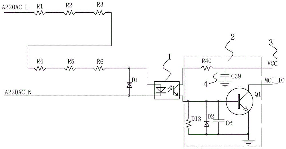
[0016] refer to figure 1 , a frequency adaptive low-voltage power carrier communication zero-crossing detection circuit of the present invention includes an MCU and a zero-crossing detection circuit, and the zero-crossing detection circuit includes an input interface and a rectifier connected in parallel to two power carrier lines of the input interface Diode D1 and opto-isolator 1, the light-emitting diode in the opto-isolator 1 is connected in parallel with the rectifier diode D1, the two power carrier lines are live wire and neutral line respectively, and the cathode of the rectifier diode D1 is connected to the live wire connection, the anode is connected to the neutral line, the parallel connection direction of the light-emitting diode in the electrical isolator is opposite to that of the rectifier diode D1, and the strong and weak currents are completely isolated by photoelectricity to ensure the safety of the system. The voltage it bears, the live line is connected in s...