
Construction technology of corrugated steel web post-welding shrinkage prestressed composite structure

A technology of corrugated steel webs and composite structures, which is applied to the direction of long-strip structural members, structural elements, building components, etc. for load-bearing, can solve the problems of shelling of steel plates and concrete, flange plates cannot shrink, etc., and achieve reduction Effect of Concrete Shrinkage Cracks and Reduction of Stress Redistribution in Composite Structures

Active Publication Date: 2015-10-14
ZHEJIANG CTB WAVEFORM STEEL WEB
View PDF4 Cites 0 Cited by
  • Summary
  • Abstract
  • Description
  • Claims
  • Application Information

AI Technical Summary

Problems solved by technology

[0003] The invention aims at the fact that the flange plate made of straight steel plates in the prior art cannot shrink when the concrete shrinks, and also bears the longitudinal compressive stress transmitted when the concrete shrinks. When the concrete shrinks and creeps after pouring, the steel plate and the concrete Shelling, even lead to cracks in the concrete, affecting the overall structural strength of the composite structure. It has a medium disadvantage. It provides a method of pouring concrete first, then welding the flange plate and the corrugated steel plate, and using the shrinkage of the flange plate and the corrugated steel plate during welding. Shrinkage and creep occur after concrete pouring to achieve the synergistic shrinkage of steel plate and concrete, which reduces the shrinkage cracks of concrete and the stress redistribution of composite structure. The construction technology of corrugated steel web shrinkage prestressed composite structure

Method used


Image

  • Construction technology of corrugated steel web post-welding shrinkage prestressed composite structure
  • Construction technology of corrugated steel web post-welding shrinkage prestressed composite structure

Examples


Embodiment 1

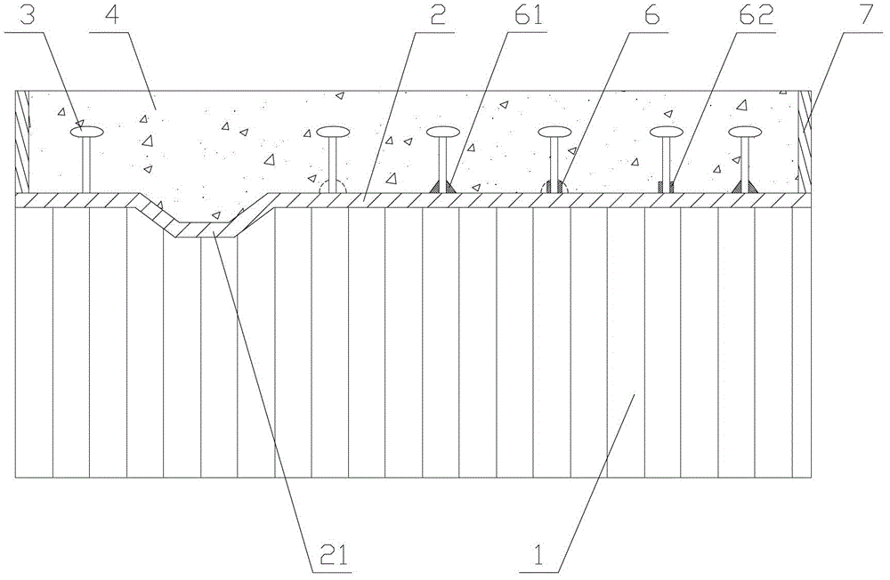
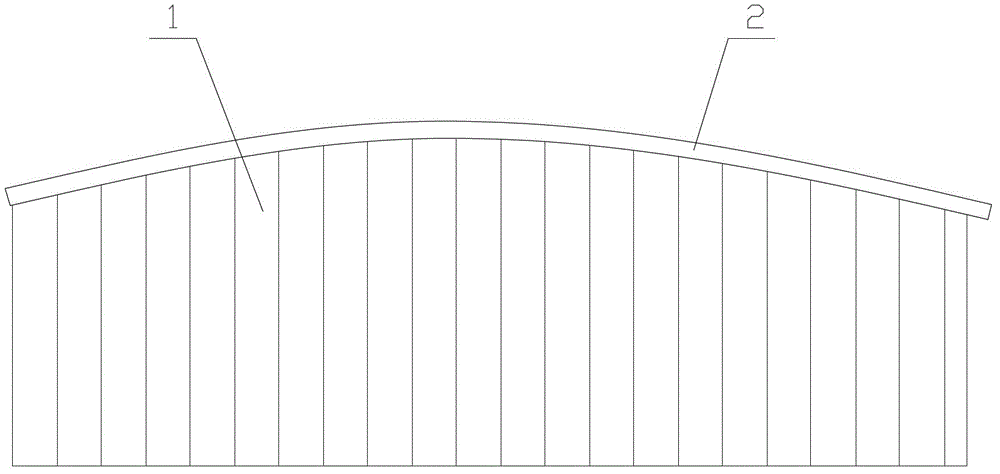
[0021] The construction technology of the post-welded shrinkage prestressed composite structure of the corrugated steel web, such as figure 1 As shown, it includes the corrugated steel web 1, the flange plate 2, and the concrete 4, including the following steps: A. Partially weld the corrugated steel web 1 and the flange plate 2; B. Pouring concrete on the flange plate 2; C , The corrugated steel web 1 and the flange plate 2 are integrally welded.

[0022] The partial welding in step A is not a complete welding, but spot welding or spaced spot welding to connect the corrugated steel web 1 and the flange plate 2 together, so that they will not fall off during installation and transportation. That is, the welding workload is small. The flange plate 2 is welded to the corrugated steel web 1 and the flange plate 2 is combined with the concrete 4. First of all, in the prior art, most of the flange plates and webs are completely welded and transported to the construction site, and then...

Embodiment 2

[0027] The difference between this embodiment and the first embodiment is that a micro strain wave 21 is provided on the flange plate 2. The flange plate 2 has a micro-shaped strain wave 21, and the two ends of the flange plate 2 are welded with a limited end plate 7. Limiting end plates 7 are arranged at both ends of the beam. By setting micro-shaped strain waves 21 on the flange plates, compared with the straight flange plate in the prior art that cannot contract longitudinally, the flange with micro-strain waves The plate 2 can shrink together with the concrete in the longitudinal direction, and the corrugated steel plate connected with the flange plate 2 has a certain longitudinal shrinkage capacity. Therefore, in the entire composite structure: the concrete, the flange plate, and the corrugated steel plate shrink together to make The entire structure can work in concert to achieve a completely combined state. The wave height of the micro-shaped strain wave 21 is less than...


PUM


Abstract

The invention relates to a corrugated steel web combined structure construction process, and discloses a corrugated steel web post-welding contraction pre-stress combined structure construction process, which involves a corrugated steel web (1), a flange plate (2), and concrete (4), and comprises the following steps: A. partially welding the corrugated steel web (1) and the flange plate (2); B. pouring concrete on the flange plate (2); C. integrally welding the corrugated steel web (1) and the flange plate (2). According to the invention, concrete is poured firstly, and the flange plate is welded with the corrugated steel web; contraction and creep of the poured concrete are resisted by the contraction of the welding of the flange plate and the corrugated steel web, thus synergetic contraction of the steel web and the concrete is realized, and concrete contraction cracks and the stress redistribute phenomenon of the combined structure are reduced.

Description

Technical field [0001] The invention relates to a construction process of a corrugated steel web composite structure, in particular to a construction process of a corrugated steel web post-welded shrinkage prestressed composite structure. Background technique [0002] At present, the concrete in the composite structure has shrinkage and creep, but the connecting key cannot be strained during the shrinkage and creep of the concrete. For example, the flange plate made of flat steel plate cannot shrink when the concrete shrinks, but also bears the shrinkage of the concrete. This patent can coordinate the change of the flange plate and the concrete to make the flange plate have a certain longitudinal shrinkage strain when the concrete shrinks, and reduce the concrete shrinkage cracks and the combined structural stress. Distribution phenomenon. Summary of the invention [0003] The present invention aims at the fact that the flange plate made of the flat steel plate in the prior art c...

Claims


Application Information

Patent Timeline
Patent Type & Authority Patents(China)
IPC IPC(8): E04C3/293E01D19/00
Inventor 孙天明董中江
Owner ZHEJIANG CTB WAVEFORM STEEL WEB
Learn More