
Combined structural-welding contracting connection structure and construction process

A combination structure and connection structure technology, which is applied to the direction of load-bearing elongated structural components, structural elements, building components, etc., can solve the problems of steel plates and concrete peeling, flange plates cannot shrink, concrete cracks, etc., to achieve Avoid shrinkage cracks, reduce stress redistribution phenomenon, and increase the effect of longitudinal expansion and contraction performance

Active Publication Date: 2014-01-08
ZHEJIANG CTB WAVEFORM STEEL WEB
View PDF3 Cites 2 Cited by
  • Summary
  • Abstract
  • Description
  • Claims
  • Application Information

AI Technical Summary

Problems solved by technology

[0003] The invention aims at the fact that the flange plate made of straight steel plates in the prior art cannot shrink when the concrete shrinks, and also bears the longitudinal compressive stress transmitted when the concrete shrinks. When the concrete shrinks and creeps after pouring, the steel plate and concrete Shelling occurs, and even leads to cracks in the concrete, which affects the overall structural strength of the combined structure. A method is provided by setting the connecting plate and welding the adjacent flange plates after the concrete is poured to make the welding of the flange plates Shrinkage and concrete creep and shrinkage occur at the same time, reducing the phenomenon of concrete shrinkage cracks and composite structure stress redistribution. The composite structure welded shrinkage connection structure and construction technology

Method used


Image

  • Combined structural-welding contracting connection structure and construction process
  • Combined structural-welding contracting connection structure and construction process

Examples


Embodiment 1

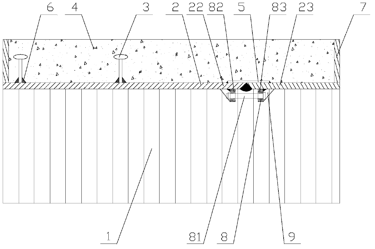
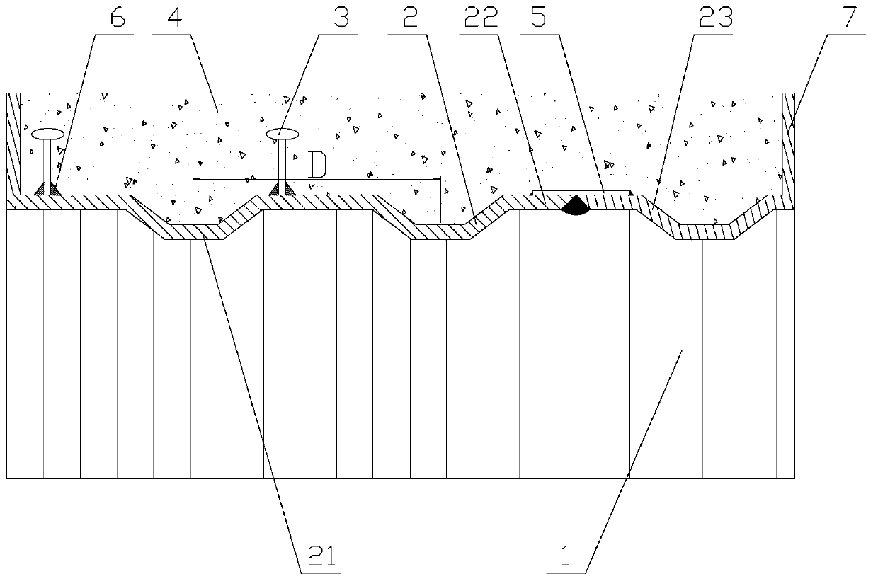
[0022] Combined structure Welded shrinkage connection structure, such as figure 1 As shown, it consists of corrugated steel web 1, flange plate 2, and concrete 4. One side of the flange plate 2 is welded with the corrugated steel web 1, and the other side is combined with concrete 4. The flange plate 2 is segmented. Open type, comprise left flange plate 22 and right flange plate 23, be welded with connecting strap 5 between left flange plate 22 and right flange plate 23, left flange plate 22 and right flange plate 23 are connected by welding. One end of the connecting strap 5 is welded to the left flange plate 22 or the right flange plate 23, and the other end is not welded, which can ensure the horizontal sliding of the flange plate 2 when it shrinks.

[0023] The two ends of the flange plate 2 are welded with a limiting end plate 7 . The connecting strap 5 is welded on the side where the flange plate 2 and the concrete 4 are connected. The connecting board also plays the r...

Embodiment 2

[0029] Such as figure 2 As shown, the difference between this embodiment and Embodiment 1 is that the distance between the left flange plate 22 and the right flange plate 23 is 16mm, and the left flange plate 22 and the right flange plate 23 at the disconnection are provided with a single-sided cutout. The left flange plate 22 is provided with a left bolt end plate 82, and the right flange plate 23 is provided with a right bolt end plate 83, and the left bolt end plate 82 and the right bolt end plate 83 are connected by high-strength bolts 81. Before the left flange plate 22 is welded to the right flange plate 23, bolts are used to reduce the disconnection distance between the left flange plate 22 and the right flange plate 23, and then welding is performed. The single-sided slit is used for welding the left flange plate 22 and the right flange plate 23 . Since the left flange plate 22 is provided with a left bolt end plate 82 and the right flange plate 23 is provided with a...


PUM


Abstract

The invention relates to a steel-concrete combined structure, and discloses a combined structural-welding contracting connection structure and a construction process. The structure comprises a corrugated steel web, flange plates, and a concrete; one surface of the flange plate is welded with the corrugated steel web, and the other surface is combined with the concrete; the flange plates comprise a left flange plate and a right flange plate; a connection approach slab is welded between the left flange plate and the right flange plate; and the left flange plate is connected with the right flange plate through welding. The process comprises: A. respectively welding the left flange plate and the right flange plate with the approach slab; B. welding the flange plates with the corrugated steel web; C. constructing concrete; D. directly welding the left flange plate with the right flange plate. According to the invention, through the arrangement of the approach slab, adjacent flange plates are welded after concrete pouring, and thus the welding contraction of the flange plates occurs simultaneously with the concrete creep and contraction; the vertical telescoping performance of connection keys is added to adapt concrete contraction and creep in the combined structure, and thus to prevent contraction crack of the concrete.

Description

technical field [0001] The invention relates to a steel-concrete composite structure, in particular to a welded shrinkage connection structure and construction technology of the composite structure. Background technique [0002] At present, the concrete in the composite structure has shrinkage and creep, but the connecting key cannot be strained during the shrinkage and creep of the concrete. For example, the flange plate made of a straight steel plate cannot shrink when the concrete shrinks, and it also bears the burden of the concrete shrinkage. The longitudinal compressive stress transmitted at the same time, this patent can change the flange plate and the concrete synergistically, and use the shrinkage effect during welding to make the flange plate have a certain strain shrinkage when the concrete shrinks, reducing the concrete shrinkage cracks and the stress redistribution of the combined structure Phenomenon. Contents of the invention [0003] The invention aims at ...

Claims


Application Information

Patent Timeline
Patent Type & Authority Applications(China)
IPC IPC(8): E04C3/293E04G21/14
Inventor 孙天明周君威
Owner ZHEJIANG CTB WAVEFORM STEEL WEB
Learn More