Automatic positioning and clamping device and method of drill rod and drill collar on pipe threading lathe

An automatic positioning and clamping device technology, applied in the field of metal cutting, can solve the problems of cumbersome procedures and low work efficiency, and achieve the effect of reducing dependence, reducing labor intensity and improving repair efficiency

Inactive Publication Date: 2014-01-15
SHENYANG POLYTECHNIC UNIV
View PDF5 Cites 10 Cited by
  • Summary
  • Abstract
  • Description
  • Claims
  • Application Information

AI Technical Summary

Problems solved by technology

[0004] Purpose of the invention: The invention provides an automatic positioning and clamping device and method for drill pipes and drill collars on a pipe thread lathe, the purpose of which is to solve the problems of cumbersome procedures and low work efficiency in the previous methods

Method used


Image

  • Automatic positioning and clamping device and method of drill rod and drill collar on pipe threading lathe

Examples


specific Embodiment approach

[0014] The specific embodiment: the invention will be further described below in conjunction with the accompanying drawings:

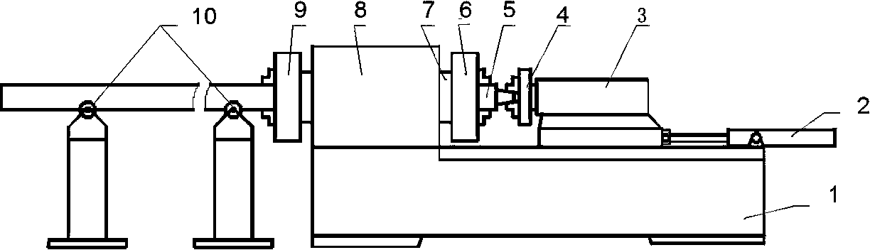
[0015] Such as figure 1 As shown, the invention provides an automatic positioning and clamping device for drill pipes and drill collars on a pipe thread lathe. Multiple sets of idler rollers 10 are arranged on one side of the bed, the bedside box 8 and the tail table 3 are arranged on the bed body, and the bedside box 8 is arranged on the side close to the multiple sets of idler rollers 10 of the bracket; the tail table 3 can be opposite Move back and forth on the bedside box 8; the main shaft 7 extending from the front and rear ends of the bedside box 8 is also provided in the bedside box 8, and the front floating chuck 6 and the rear centering chuck are respectively arranged on the front and rear ends of the main shaft 7. The chuck 9; the main shaft 7 is a hollow structure for the workpiece to pass through; the end of the tail table 3 facing the hea...


PUM


Abstract

The invention provides an automatic positioning and clamping device of a drill rod and a drill collar on a pipe threading lathe. The device comprises a lathe bed, a tail platform, a headstock and a bracket multi-group carrier roller. The bracket multi-group carrier roller is arranged on one side of the lathe bed, the headstock and the tail platform are arranged on the lathe bed, and the headstock (8) is arranged on one side close to the bracket multi-group carrier roller (10). According to the device and method, automatic feeding, positioning, clamping and discharging of workpieces can be achieved. The purpose of the device and method is to achieve the full-automatic machining processes, including feeding and discharging, of the numerical control pipe threading lathe.

Description

technical field [0001] The invention is used in the field of metal cutting and processing, and relates to a pipe thread lathe, which takes the axis line of the old thread as a reference before repairing and turning the old internal and external threads at both ends of long pipe workpieces such as used petroleum drill pipes and drill collars. Automatic positioning, clamping, and automatic loading and unloading devices. Background technique [0002] In the petroleum and geological drilling industry, the drill bits that are drilled into the ground thousands of meters deep are composed of hundreds of drill pipes and drill collars, which are screwed one by one by the threads at both ends, and connected to the ground drilling rig. The ground drilling rig passes through these The drill pipe and drill collar transmit the torque to the drill bit. These drill pipes and drill collars need to be unloaded one by one after completing the drilling work of a well, recovered, repaired, and...

Claims


Application Information

Patent Timeline
Patent Type & Authority Applications(China)
IPC IPC(8): B23B15/00B23B31/02
CPCB23Q7/055B23B31/023
Inventor 孙兴伟王可
Owner SHENYANG POLYTECHNIC UNIV
Why Eureka
Try Eureka