Swill barrel

A technology for swill buckets and bucket lids, which is applied in the field of public health applications and can solve problems such as inclusions, difficulty in removal, and strange smells

Active Publication Date: 2015-06-03
顾昌
View PDF6 Cites 0 Cited by
  • Summary
  • Abstract
  • Description
  • Claims
  • Application Information

AI Technical Summary

Problems solved by technology

Swill is mainly formed by mixing leftovers into swill buckets when restaurants and restaurants dispose of discarded leftovers. It is rich in water, nutrients and oil, and is easily fermented to produce an unpleasant smell; especially It is a vehicle for transporting swill. Although it tries to avoid the peak period of people's travel, it will often appear in people's field of vision, mixed with an unpleasant smell, which not only spoils people's mood, but also makes people lose their appetite. Moreover, due to the large amount of water in the swill, it often drips down during transportation, forming black spots on the road, which is difficult to remove, and also emits a strange smell for a long time

Method used


Image

  • Swill barrel

Examples


Embodiment 1

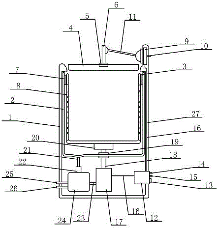
[0017] When processing the swill in the de-juicing tank, the restaurant staff presses the de-juicing control switch, the circuit control device starts to work according to the set program, and first sends current to the bung cover control device to ensure that the bung cover control device controls the bung cover. In the closed position; then send current to the power device, the power device starts to work according to the set program, the power output by the power device is sent to the rotating device through the power output shaft, and the rotating device drives the dejuicing barrel to rotate rapidly; under the centrifugal force Under the action, the juice in the swill is thrown out to the cavity wall between the de-juicing barrel and the inner barrel through the stainless steel filter plate, and flows along the cavity wall into the cavity between the de-juicing barrel and the bottom of the inner barrel.

Embodiment 2

[0019] When processing the swill in the de-juicing tank, the restaurant staff presses the de-juicing control switch, the circuit control device starts to work according to the set program, and first sends current to the bung cover control device to ensure that the bung cover control device controls the bung cover. In the closed position; then send current to the power device, the power device starts to work according to the set program, the power output by the power device is sent to the rotating device through the power output shaft, and the rotating device drives the dejuicing barrel to rotate rapidly; under the centrifugal force Under the action, the juice in the swill is thrown out to the cavity wall between the dejuicing barrel and the inner barrel through the carbon steel filter plate, and flows along the cavity wall into the cavity between the dejuicing barrel and the bottom of the inner barrel.


PUM


Abstract

The invention relates to a swill barrel and belongs to the technical field of public health application. A restaurant worker can press a barrel cover control switch to control a barrel cover to be opened and pour collected swill into a juice removing barrel and can press the barrel cover control switch again to control the barrel cover to be closed to prevent smell of the swill to drift away. After a juice removing switch is pressed, a rotating device drives the juice removing barrel to rotate fast, and juice in the swill is tossed to the cavity wall between the juice removing barrel and an inner barrel through a filtering plate under the effect of centrifugal force and flow into a cavity between the bottoms of the juice removing barrel and the inner barrel along the cavity wall. The juice in the cavity between the bottoms of the juice removing barrel and the inner barrel flows into an oil water separation device with limited quantity through a flow guide pipe by a quantity control device. An oil water separation control switch is pressed, a circuit control device supplies power to a power device according to set program, the power device provides power for the oil water separation device through a second power transmission shaft, and the oil water separation device separates oil and water in the juice.

Description

technical field [0001] The invention relates to a swill bucket, which belongs to the technical field of public health applications. Background technique [0002] Even in a big city with a strong modern atmosphere, when a vehicle transporting swill passes by, it will emit a nasty smell, causing people to dodge around, and the good impression of the big city is gone. Swill is mainly formed by pouring leftovers into swill buckets when restaurants and restaurants dispose of discarded leftovers. It is rich in water, nutrients and oil, and is easily fermented to produce an unpleasant smell; especially It is a vehicle for transporting swill. Although it tries to avoid the peak period of people's travel, it will often appear in people's field of vision, mixed with an unpleasant smell, which not only spoils people's mood, but also makes people lose their appetite. and, because there is a large amount of moisture in the swill, it often drips down during transportation, forming black ...

Claims


Application Information

Patent Timeline
Patent Type & Authority Patents(China)
IPC IPC(8): B65F1/00B65F1/14B65F1/16
CPCY02W30/10
Inventor 缪江桥
Owner 顾昌
Why Eureka
Try Eureka