Chip card fixture structure and electronic device with same

A technology of electronic devices and chip cards, which is applied in the direction of coupling devices, telephone structures, components of connecting devices, etc., and can solve problems such as troublesome installation and removal of chip cards

Inactive Publication Date: 2014-02-12
SHENZHEN FUTAIHONG PRECISION IND CO LTD
View PDF0 Cites 21 Cited by
  • Summary
  • Abstract
  • Description
  • Claims
  • Application Information

AI Technical Summary

Problems solved by technology

At the same time, the tray part is exposed outside the card slot and is covered by the cover plate. When the chip card needs to be replaced, the user opens the cover plate with his fingers and directly presses the part of the tray exposed outside the card slot to make the tray Drive the chip card to slide out from the card slot, so it is more troublesome to install and take out the chip card

Method used


Image

  • Chip card fixture structure and electronic device with same
  • Chip card fixture structure and electronic device with same
  • Chip card fixture structure and electronic device with same

Examples


Embodiment Construction

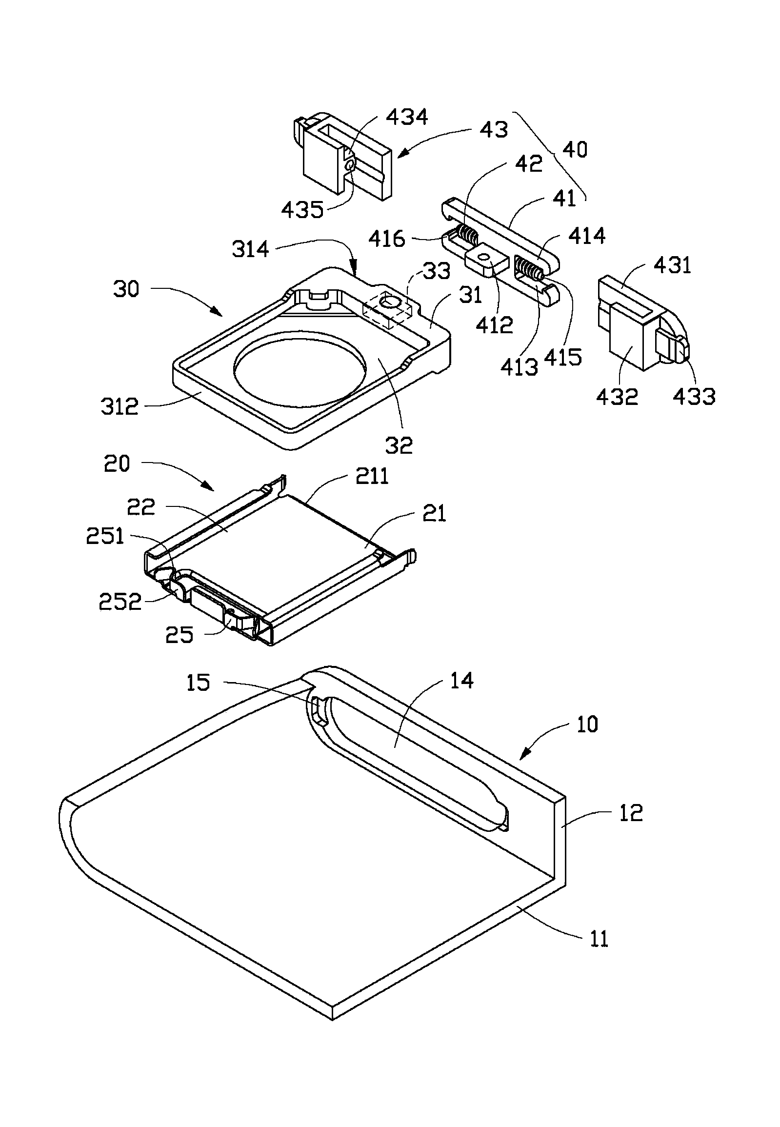
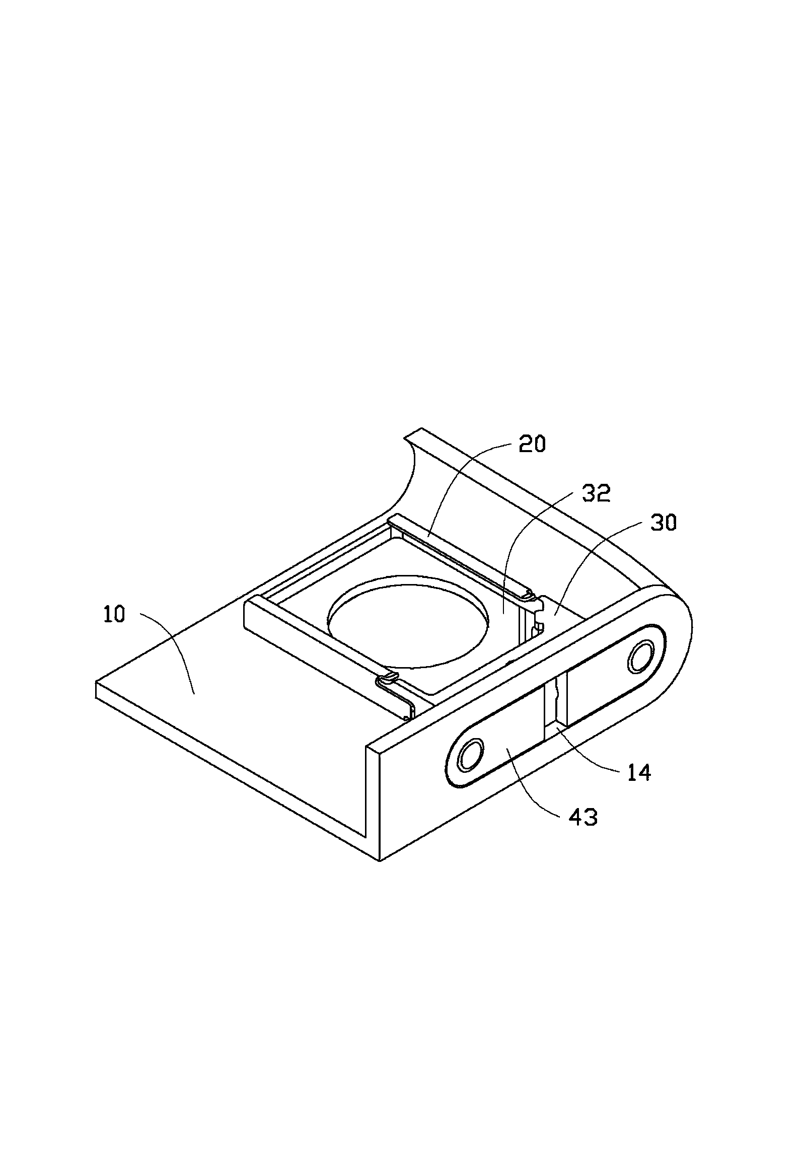
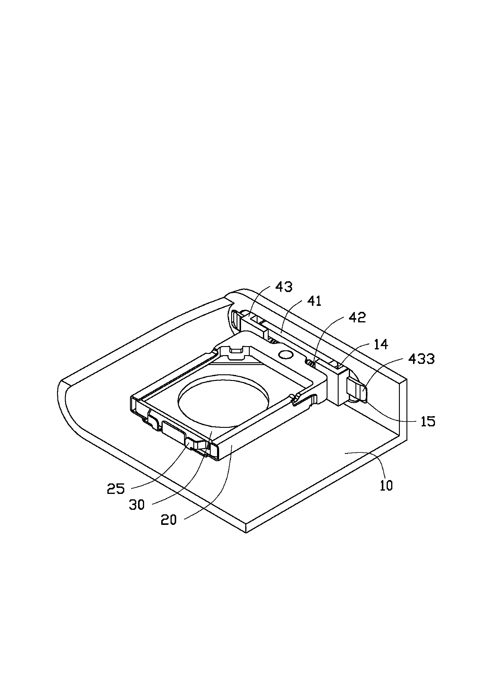
[0016] see figure 1 , The chip card holding structure of the preferred embodiment of the present invention is used in electronic devices such as mobile phones. The electronic device includes a body 10 . The chip card holding structure includes a carrier plate 20 , at least one pop-up member 25 mounted on the carrier plate 20 , a tray 30 slidably mounted on the carrier plate 20 , and a locking member 40 mounted on the tray 30 . A chip card such as a SIM card or a memory card can be installed on the body 10 through the carrier plate 20 and the tray 30. The tray 30 is locked in the body 10 by the locking member 40. After the locking member 40 is unlocked, the pop-up The part 25 is ejected from the body 10 through the tray 30 .

[0017] The body 10 is a casing of an electronic device, and includes a bottom wall 11 and an end wall 12 . The end wall 12 is disposed on the periphery of the bottom wall 11 . The end wall 12 defines a long slot 14 . Both ends (not shown) of the thro...


PUM


Abstract

A chip card holder includes a housing, a receiving frame, an ejecting member, a tray, a protective cover, and two sliders. The housing defines a through hole and two latching grooves. The receiving frame is mounted on the housing. The ejecting member is positioned at one end of the receiving frame. The tray is slidably received in the receiving frame and abutted by the ejecting member. The protective cover is mounted to the tray and received in the through hole. The two sliders are slidably positioned on the protective cover and releasbly received in the latching grooves. When the two sliders slide relative to the protective cover and are unlocked from the housing, the ejecting member ejects the tray from the housing.

Description

technical field [0001] The invention relates to a chip card holding structure and an electronic device with the chip card holding structure. Background technique [0002] Most mobile phones design the chip card fixing structure under the battery, but this structure is not suitable for the trend of thinning mobile phones, and the SIM card is prone to collision and wear due to frequent battery replacement. In order to overcome the above disadvantages, the chip cards of some mobile phones are generally accommodated in a card slot of the mobile phone through a tray. At the same time, the tray part is exposed outside the card slot and is covered by the cover plate. When the chip card needs to be replaced, the user’s finger opens the cover plate and directly presses the part of the tray exposed outside the card slot to make the tray The chip card is driven to slide out from the card slot, which is troublesome when loading and unloading the chip card. Contents of the invention ...

Claims


Application Information

Patent Timeline
Patent Type & Authority Applications(China)
IPC IPC(8): H01R13/629H01R13/635H01R13/639H01R12/71H04M1/02
CPCG06K13/0831H05K5/0091
Inventor 高彦岭
Owner SHENZHEN FUTAIHONG PRECISION IND CO LTD
Why Eureka
Try Eureka