Electric connector

A technology of electrical connectors, connectors, applied in the direction of connections, two-part connection devices, circuits, etc.

Inactive Publication Date: 2014-02-12
HIROSE ELECTRIC GROUP
View PDF6 Cites 0 Cited by
  • Summary
  • Abstract
  • Description
  • Claims
  • Application Information

AI Technical Summary

Problems solved by technology

[0008] On the other hand, there are cases where the lock is released unexpectedly due to an accident

Method used


Image

  • Electric connector
  • Electric connector
  • Electric connector

Examples


Embodiment Construction

[0039] Hereinafter, a preferred embodiment of the present invention will be described with reference to the drawings.

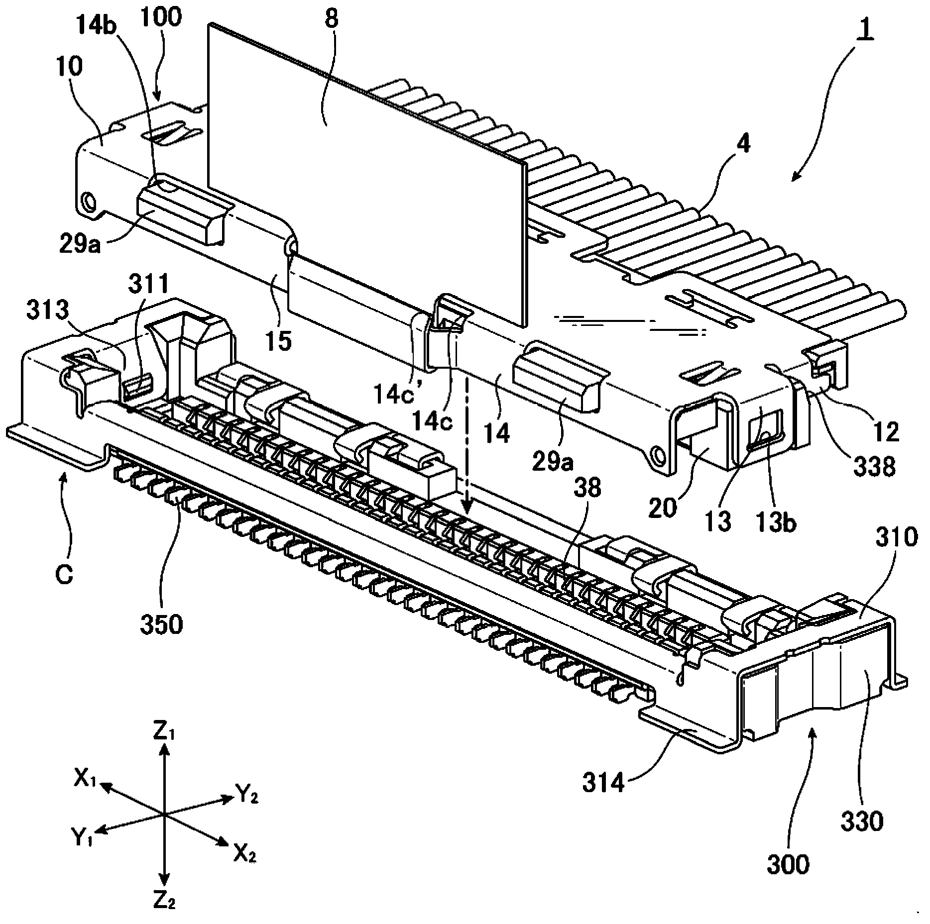
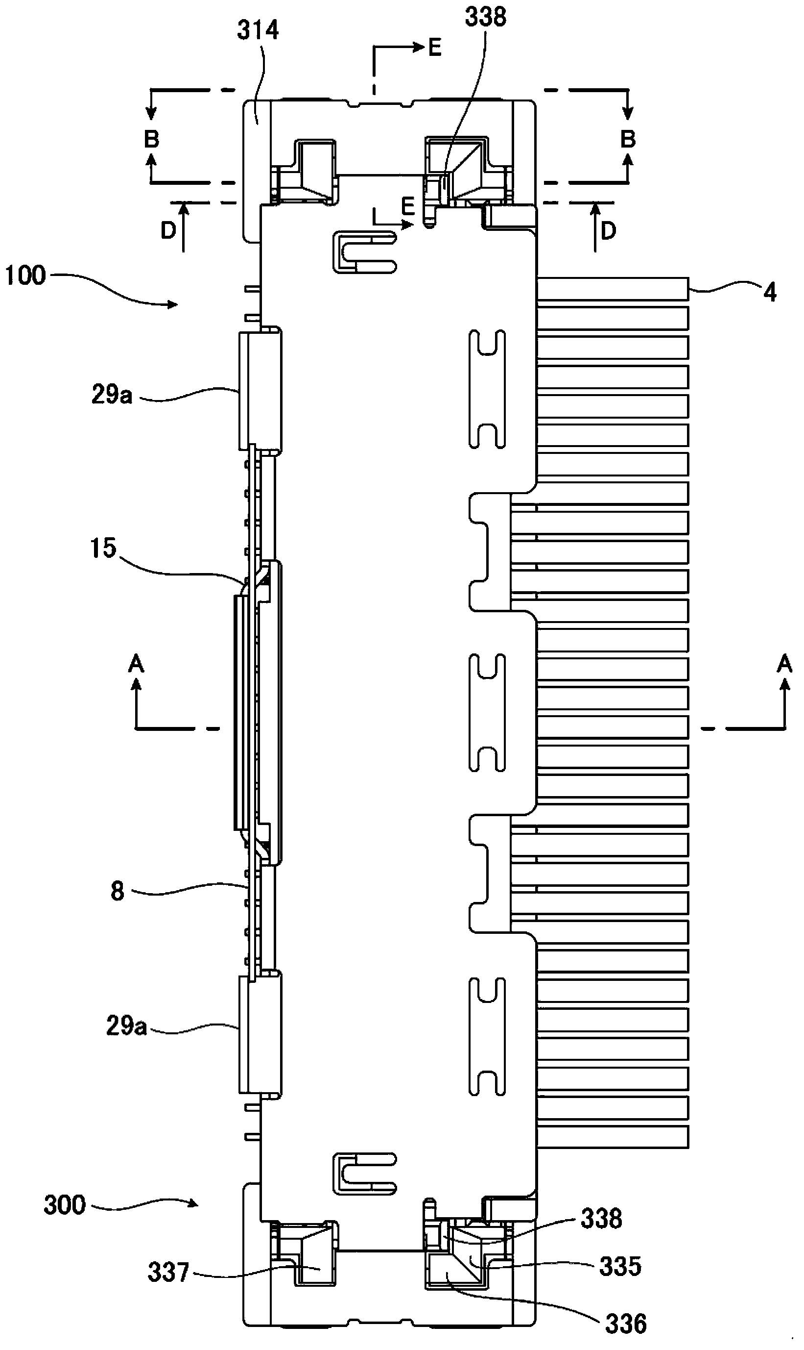
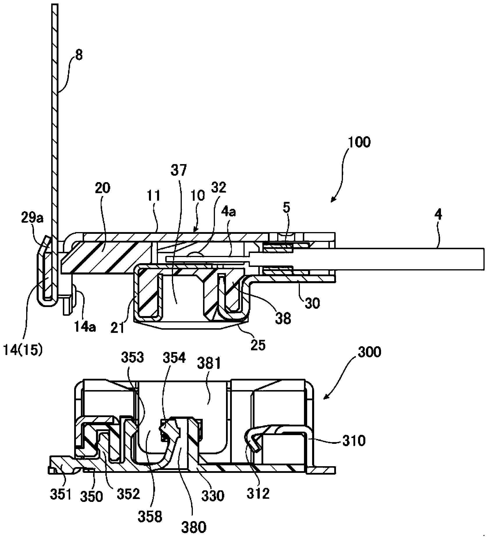
[0040] The electrical connector 1 of the present invention is composed of a set of a cable-side connector 100 and a board-side connector 300 that can be fitted in a vertical direction. figure 1 It is an upper perspective view showing the state before the cable-side connector 100 and the board-side connector 300 are fitted, figure 2 It is a plan view which shows the state after these fitting. When mating, along the horizontal direction ( figure 1 The bottom surface of the cable-side connector 100 extending in the “Y” direction) and the upper surface of the board-side connector 300 also extending in the horizontal direction abut each other.

[0041] Both the cable-side connector 100 and the substrate-side connector 300 are arranged along the long side direction ( figure 1 The "X" direction) is set in a state extending, and has a left-right symmetrical sh...


PUM


Abstract

The present invention provides an electric connector. When force is applied to a plug connector along the direction of relieving the lock at one side where a cable is installed, the lock is difficult to be relieved, when the same force is applied to the plug connector at the other side, the lock can be relieved successfully. The connector consists of a first connector and a second connector which can be embedded with each other in a perpendicular direction. At a lateral side of the each connector and in the middle of the other side and one side, a first locking part and a second locking part for locking the first connector and the second connector are respectively provided. The first locking part is provided with a boss, the second locking part is provided with a recess, and the boss is embedded in the recess during embedding. After the locking, in the case of applying force along the direction of relieving the lock, the boss and the recess partially collide to generate a counter force which withstands the force for relieving, the counter force of the boss and the recess at the other side is less than the counter force at one side.

Description

technical field [0001] The present invention relates to an electrical connector composed of a set of connectors that can be fitted to each other, and more specifically, to an electrical connector that can lock the fitting of the connectors. Background technique [0002] Along with the miniaturization of personal computers and portable electronic devices, the miniaturization of electronic components is progressing. As the miniaturization of electronic components advances, their handling becomes difficult. Such electronic components include, for example, thin-wire coaxial cable connectors. [0003] Figure 12 In FIG. 1 , an example of a conventional thin-wire coaxial cable connector disclosed in JP 2011-138687 A is shown by a perspective view. The connector consists of a vertically mated plug connector 120 ( Figure 12 (a)) with receptacle connector 110 ( Figure 12 (b)) group composition. During mating, the bottom surface of the plug connector 120 extending in the horizont...

Claims


Application Information

Patent Timeline
Patent Type & Authority Applications(China)
IPC IPC(8): H01R13/639H01R13/629H01R13/64
CPCH01R13/6485H01R24/00
Inventor 伝法谷郁夫
Owner HIROSE ELECTRIC GROUP
Why Eureka
Try Eureka