
Zero-point energy power machine

A mechanical and dynamic technology, applied in the field of zero-point energy dynamics

Inactive Publication Date: 2014-03-05
陈明轩
View PDF0 Cites 0 Cited by
  • Summary
  • Abstract
  • Description
  • Claims
  • Application Information

AI Technical Summary

Benefits of technology

This patented technology allows for an electric motor that uses less electrical current compared to traditional motors while also producing more powerful torque without adding extra weight or complexity. It achieves this through use of specific types of materials called permanently excited rare earth (Eu) neodymium iron boron sinters ("NdFeB") which are used instead of expensive copper wire rods. By cutting off AC lines around certain areas inside these NdFe B material, it becomes possible to generate high levels of magneism at very low voltages relative to other methods like induction heating. Overall, this innovation makes machines stronger but lighterweight and efficient over time.

Problems solved by technology

This patented technical problem addressed by the inventors relates to finding an ideal way for creating powerful machines without relying on extra materials like magnetism.

Method used


Image

  • Zero-point energy power machine
  • Zero-point energy power machine
  • Zero-point energy power machine

Examples


Embodiment Construction

[0021] The present invention will be described in further detail below through specific implementation examples and in conjunction with the accompanying drawings.

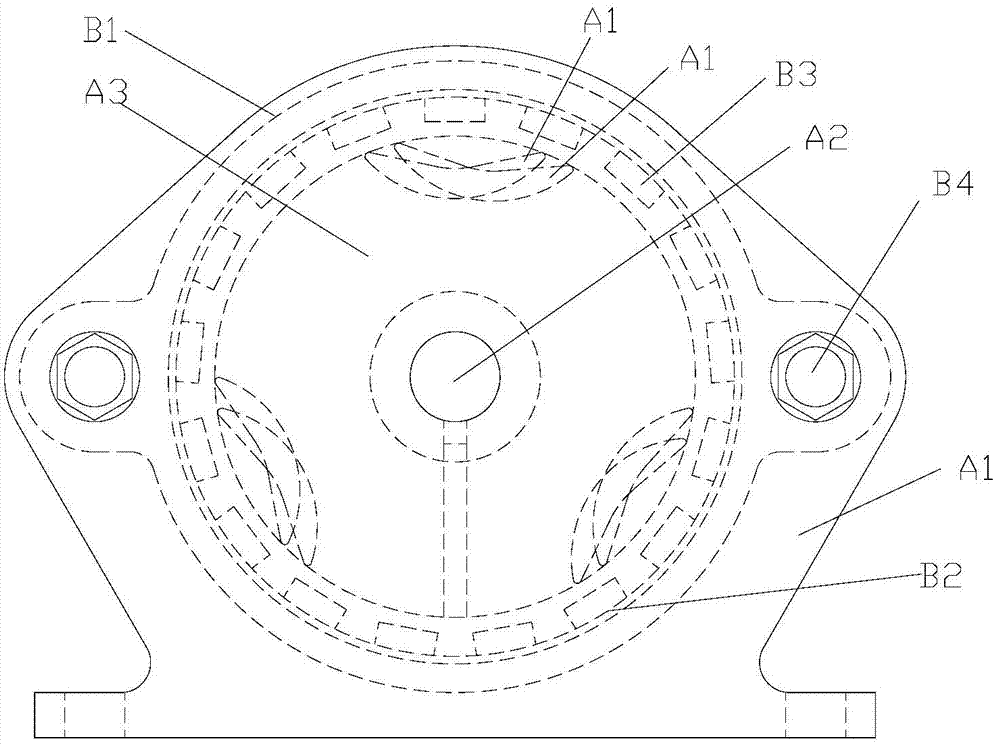
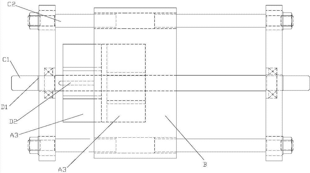
[0022] An embodiment of the present invention provides a zero-point energy power machine, including:

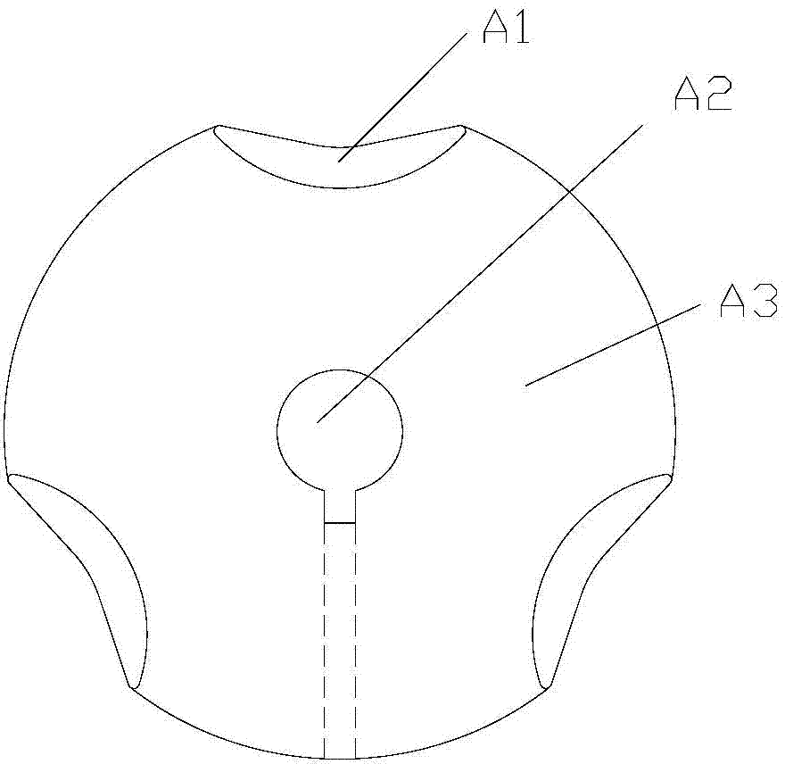
[0023] More than one sub-rotor, the sub-rotor is provided with a through hole passing through the center, all the sub-rotors are connected through the central shaft, and the central shaft passes through the through hole and is fixedly connected with the sub-rotor; The outer surface of the sub-rotor is provided with a plurality of grooves, and arcuate permanent magnets are arranged in the grooves; the central shaft is connected to the external transmission assembly as a power output shaft;

[0024] The outer cover is in the shape of a cylinder and covers the outside of the sub-rotor. Its central axis is coaxial with the central axis, and a plurality of bar magnets are evenly distributed on its inner wall. The outer...


PUM


Abstract

The invention relates to the field of power machines, in particular to a zero-point energy power machine. The zero-point energy power machine comprises more than one branch rotor, a through hole penetrating the center is formed in each branch rotor, all the branch rotors are connected through a middle shaft, and the middle shaft penetrates through the through holes and is fixedly connected with the branch rotors. A plurality of grooves are formed in the outer surfaces of the branch rotors, and arch-shaped permanent magnets are arranged in the grooves. The middle shaft is used as a power output shaft and is connected with an external transmission component. Outer covers are cylindrical and cover the outer portions of the branch rotors, the central shafts of the outer covers are coaxial with the middle shaft, a plurality of strip-shaped magnets are evenly distributed on the inner walls of the outer covers, the outer covers slide in the axial direction, and are connected with supporting pieces through relative sliding connecting pieces. The zero-point energy power machine can generate driving force far larger than bearing resistance to enable the rotors to rotate.

Description


Claims


Application Information

Patent Timeline
Owner 陈明轩
Learn More