Flexible continuous-body mechanical structure capable of being bent and telescopic

A mechanical structure and continuum technology, applied in the direction of manipulators, claw arms, manufacturing tools, etc., can solve problems such as large size, difficult transmission arrangement, and complicated structure

Active Publication Date: 2014-04-09
BEIJING SURGERII TECH CO LTD
View PDF9 Cites 80 Cited by
  • Summary
  • Abstract
  • Description
  • Claims
  • Application Information

AI Technical Summary

Problems solved by technology

When multiple independent turning motions are connected in series through this structure, it is generally necessary to install a drive unit (such as a motor...

Method used


Image

  • Flexible continuous-body mechanical structure capable of being bent and telescopic
  • Flexible continuous-body mechanical structure capable of being bent and telescopic
  • Flexible continuous-body mechanical structure capable of being bent and telescopic

Examples


Embodiment 1

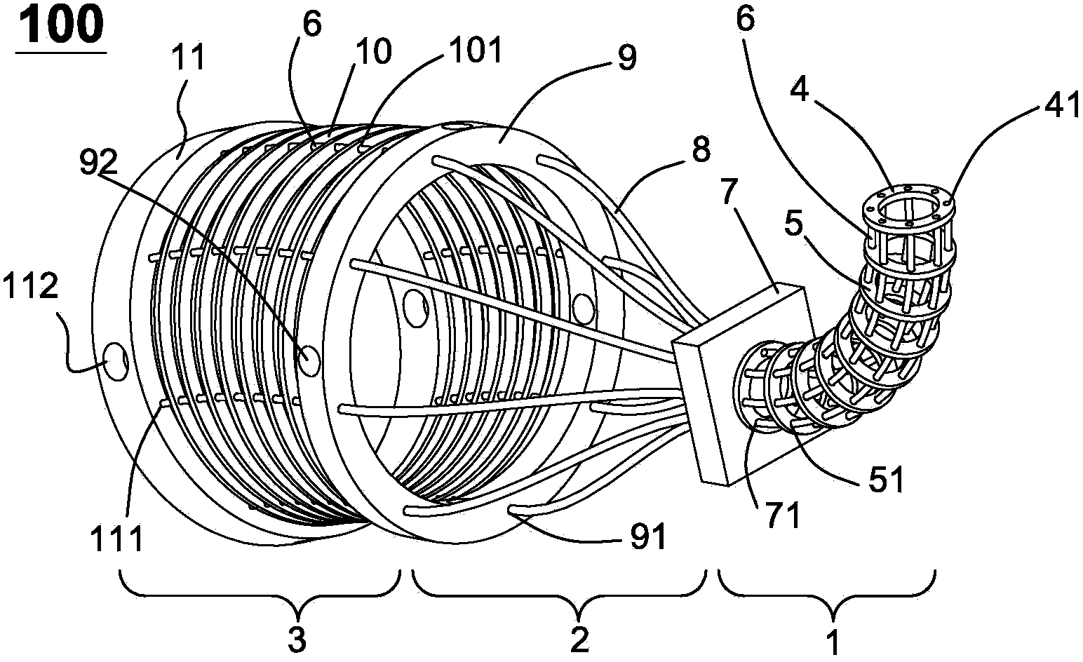
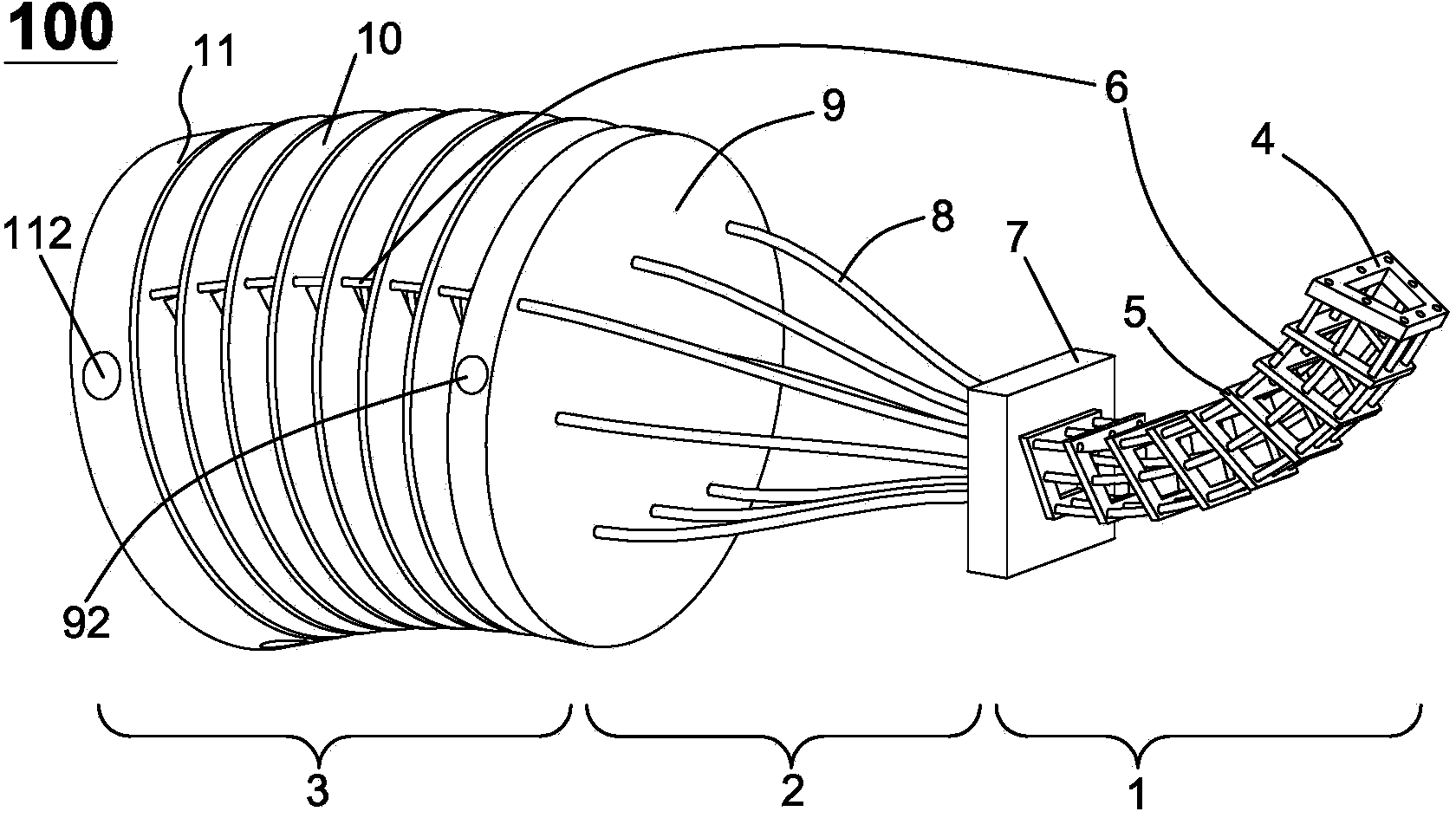
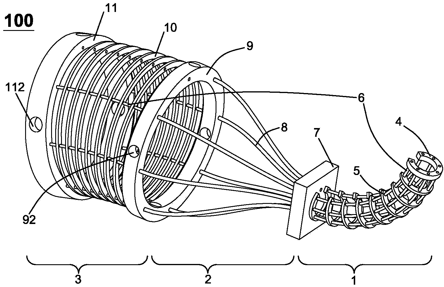
[0094] figure 1 A perspective view showing the first embodiment of the flexible continuum mechanical structure according to the present invention. Such as figure 1 , the flexible continuum mechanical structure 100 is composed of a distal structure body 1 , a middle connecting body 2 and a proximal structure body 3 . The distal structure 1 includes a distal locking disc 4, a distal spacer 5 and a structural bone 6, the middle connecting body 2 includes pipe fixing plates 7, 9 and a pipe 8, and the proximal structure 3 includes a proximal spacer 10, The proximal locking disc 11 and the structural bone 6. In this embodiment, the structural bone 6 on the distal structure 1 and the corresponding structural bone 6 on the proximal structure are the same structural bone, but those skilled in the art should understand that the structure on the distal structure 1 The bone and the corresponding structural bone 6 on the proximal structural body may also be not the same structural bone,...

Embodiment 2

[0107] Figure 10 A structural diagram showing the second embodiment of the flexible continuum mechanical structure according to the present invention. In this embodiment, the flexible continuum mechanical structure can be sequentially extended to form a multi-segment continuum mechanical structure, that is, a multi-segment proximal structure and / or a multi-segment distal structure can be sequentially extended. Figure 10 The embodiment shown in is extended with two proximal structure bodies and two distal structure bodies, which share a central connecting body. Among them, the basic structure of each proximal structure, distal structure, and middle connector figure 1 The illustrated embodiment is the same and will not be described in detail here.

[0108] Such as Figure 10 As shown, the No. 1 proximal structure 3 and the No. 1 distal structure 1 constitute the No. 1 continuum mechanical structure, while the No. 2 proximal structure 19 and the No. 2 distal structure 18 con...

Embodiment 3

[0115] Figure 15-16A structural diagram showing a third embodiment of the flexible continuum mechanical structure according to the present invention. In this embodiment, the main difference from Embodiment 2 is that a first distal kinematic chain 1a' and a second distal kinematic chain 1a' and a second distal The end kinematic chains 18a' are respectively used to enhance the rigidity, especially the torsional strength, of the No. 1 distal structure body 1' and the No. 2 distal structure body 18'. The first distal-end kinematic chain 1a' and the second distal-end kinematic chain 18a' respectively maintain compatible motion capabilities or motion compatibility with the No. 1 distal-end structure 1' and the No. 2 distal-end structure 18', thereby Can bend and stretch with it. Herein, maintaining compatible mobility or maintaining motion compatibility means that the implantation of the distal kinematic chain does not impede the movement of the distal structure, even if it local...


PUM


Abstract

The invention relates to a flexible continuous-body mechanical structure capable of being bent and telescopic. The flexible continuous-body mechanical structure comprises a far structure body, a near structure body and a middle connection body. The far structure body comprises a far partition body, a far locking plate, a structure frame and a far moving chain. The near structure body comprises a near partition body, a near locking plate and a structure frame. The far structure body is related to the near structure body through the middle connection body, and one end of the structure frames are fixed on the near locking plate, sequentially penetrates through the near partition plate, the middle connection body and the far partition plate, and is fixed on the far locking plate, so that when the near structure body is driven to be bent and/or telescopic in any direction, the far structure body is correspondingly bent and/or telescopic in the opposite direction. The flexible continuous-body mechanical structure can be bent and/or telescopic in any direction by means of the very simple structure bodies and has very wide purposes.

Description

technical field [0001] The invention relates to the fields of medical equipment, industrial automation and the like, in particular to a bendable and stretchable flexible continuum mechanical structure used for medical equipment, industrial automation equipment and the like. Background technique [0002] In the existing bendable mechanical structure, the controllable bending motion is basically realized by the relative rotation at the hinge joint through two rigid or flexible links hinged to each other. When multiple independent turning motions are connected in series through this structure, it is generally necessary to install a drive unit (such as a motor, hydraulic ejector, etc.) The load of the end drive unit will make the realization of this function relatively complicated in structure and relatively large in size. [0003] In medical operations or industrial deep cavity detection, etc., it is necessary to construct instruments with multiple degrees of freedom and multi...

Claims


Application Information

Patent Timeline
IPC IPC(8): B25J18/04
Inventor 汪雯
Owner BEIJING SURGERII TECH CO LTD
Why Eureka
Try Eureka