Rotary cycle switching air valve of multi-tower air dehumidifier

A technology of air dehumidification and air valve, applied in multi-way valves, valve devices, mechanical equipment, etc., can solve problems such as temperature and humidity fluctuations, large temperature and humidity fluctuations, etc., to avoid fluctuations in temperature and humidity, simple structure, and reduce wind blowing The effect of the phenomenon

Active Publication Date: 2016-02-17
TIANJIN JINHANG COMP TECH RES INST
View PDF6 Cites 0 Cited by
  • Summary
  • Abstract
  • Description
  • Claims
  • Application Information

AI Technical Summary

Problems solved by technology

[0002] In the existing technology, there is a "double-tower switching molecular sieve dehumidifier", the switching of a pair of air valves is a reciprocating synchronous switching, so the dehumidified space has large temperature and humidity fluctuations when the air valves are switched during work; "Three The air valve of the barrel cycle switching molecular sieve dehumidifier is a combination of three pairs of air valves. In addition to temperature and humidity fluctuations during switching, a complex piping system is also required

Method used


Image

  • Rotary cycle switching air valve of multi-tower air dehumidifier
  • Rotary cycle switching air valve of multi-tower air dehumidifier
  • Rotary cycle switching air valve of multi-tower air dehumidifier

Examples


Embodiment 1)

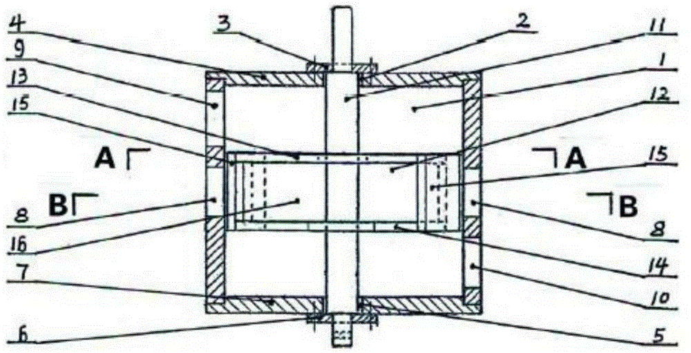
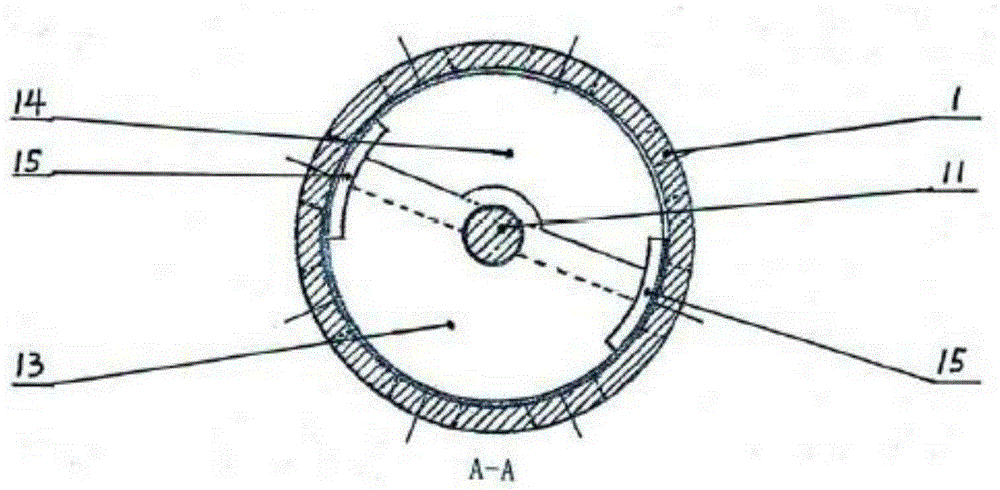
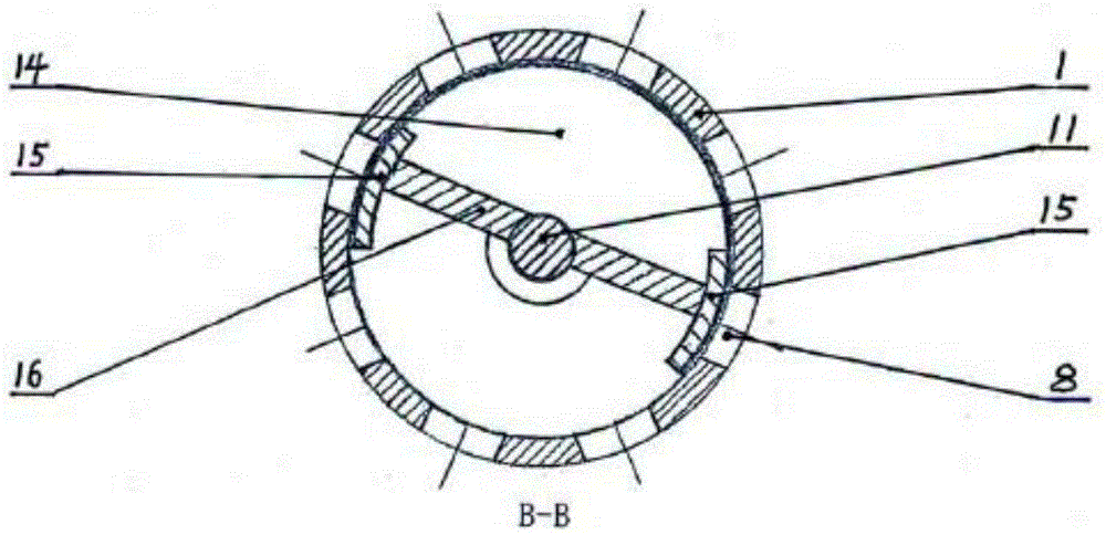
[0018] See Figures 1 to 4 The top of the cylindrical valve body 1 of the rotary cycle switching air valve of the multi-tower air dehumidifier in this embodiment is provided with an upper valve cover 4 with a central hole 2 at the center and an upper sliding bearing 3, and the bottom is provided with There is a lower valve cover 7 with a central hole 5 in the center and a lower sliding bearing 6. There are 8 identical switching air outlets 8 evenly distributed at the same height in the middle of the valve body 1. An upper air outlet 9 is provided on one side of the upper part. The other side of the lower part is provided with a lower tuyere 10; the valve stem 11 is installed in the cavity of the valve body 1 to pass through the upper sliding bearing 3 and the lower sliding bearing 6. place; one side of the upper part of the valve core 12 is provided with a flat semi-circular or fan-shaped (semi-circular in this embodiment) upper valve plate 13, and the other side of the lower ...


PUM


Abstract

The invention discloses a rotating circulating switching air valve of a multi-tower air dehumidifier. An upper valve cover and a lower valve cover are arranged at the top and the bottom of a cylindrical valve body respectively, and the centers of the upper valve cover and the lower valve cover are provided with center holes and sliding bearings. At least four identical switching air openings are evenly distributed at the same height in the middle of the valve body, and an upper air opening and a lower air opening are formed in one side at the upper portion and the other side of the lower portion of the valve body respectively. A valve element which is arranged at the corresponding position of the switching air opening in a valve body cavity comprises a valve rod, an upper valve plate, a lower valve plate, two arc valve clacks and air separating plates, the valve rod penetrates through the upper sliding bearing and the lower sliding bearing, the upper valve plate and the lower valve plate are in a circular or sector shape and are arranged on the two sides of the valve rod separately and horizontally, the distance between the upper surface and the lower surface is larger than the height of the switching air opening, the two arc valve clacks are connected with the two sides of the upper valve clack and the two sides of the lower valve clack respectively, the heights and the widths are larger than those of the switching air opening, and the air separating plates are connected with the upper valve plate and the lower valve plate and connected with the two arc valve clacks and the valve rod. The rotating circular face of the valve element is in small clearance fit with the circular face of a relevant section of the valve body inner cavity in a rotating mode.

Description

technical field [0001] The invention belongs to the field of air humidity regulation, and in particular relates to a rotary cycle switching air valve of a multi-tower air dehumidifier. Background technique [0002] In the existing technology, there is a "double-tower switching molecular sieve dehumidifier", the switching of a pair of air valves is a reciprocating synchronous switching, so the dehumidified space has large temperature and humidity fluctuations when the air valves are switched during work; "Three The air valve of the barrel cycle switching molecular sieve dehumidifier is a combination of three pairs of air valves. In addition to temperature and humidity fluctuations during switching, a complex piping system needs to be configured. Contents of the invention [0003] The technical problem to be solved by the present invention is to provide a rotary cycle switching air valve of a multi-tower air dehumidifier that can switch between multiple towers, has simple an...

Claims


Application Information

Patent Timeline
Patent Type & Authority Patents(China)
IPC IPC(8): F16K11/065
CPCF16K11/0525
Inventor 王斌王毅
Owner TIANJIN JINHANG COMP TECH RES INST
Why Eureka
Try Eureka