Improved automatic slurry grinding machine

A refiner and automatic technology, applied in cocoa, grain processing, food science, etc., can solve the problems of sticky bottom, excessive up and down jump, long cleaning tools, etc., to improve work efficiency, quality and function Simplified button keys and convenient cleaning operation

Inactive Publication Date: 2014-04-23
文树雄 +3
View PDF7 Cites 4 Cited by
  • Summary
  • Abstract
  • Description
  • Claims
  • Application Information

AI Technical Summary

Problems solved by technology

[0006] (1) After the clean water is added to the liquid hopper 17A, it flows directly into the material hole 13B through the opening 17D. The water flow is not adjusted by a device, and it is inconvenient to use when grinding food;
[0007] (2) The locking screw 16 indirectly locks the upper grinding disc 13 by squeezing the locking rubber sleeve 15. During extrusion, due to the large deformation of the locking rubber sleeve 15, the upper grinding disc 13 cannot be effectively locked, and the upper grinding disc 13 and The gap between the lower grinding discs 11 fluctuates too much up and down, and the thickness of the ground slurry cannot be effectively controlled;
[0008] (3) After the upper grinding disc 13 is removed, since the distance between the outer circular edge of the lower grinding disc 11 and the inner circular edge of the upper mouth of the pulp storage tank 1 is very narrow, the hands cannot be directly inserted into the slurry storage tank 1 for cleaning and sticking on the The residue on the pulp storage tank 1, the lower grinding disc pillar 7, and the heating plate 6; therefore, only a long-handled cleaning tool can only be used to extend into the slurry storage tank 1 for cleaning. Because the handle of the cleaning tool is relatively long and the force is not enough, often It is very difficult to clean the residues, especially the residues adhering to the top of the heating plate 6 and the inner corner of the bottom of the pulp storage tank 1
[0010] (5) The slurry is in a static state during the heating process, and the small particles of the slurry are easy to stick and agglomerate, and the heating is uneven, and the bottom is prone to appear, which affects the quality of the drink;
[0011] (6) The function keys in the control circuit board 29 are complicated, and there is no difference in heating and cooking the slurry of different foods, which affects the quality of the slurry drink

Method used


Image

  • Improved automatic slurry grinding machine
  • Improved automatic slurry grinding machine
  • Improved automatic slurry grinding machine

Examples


Embodiment Construction

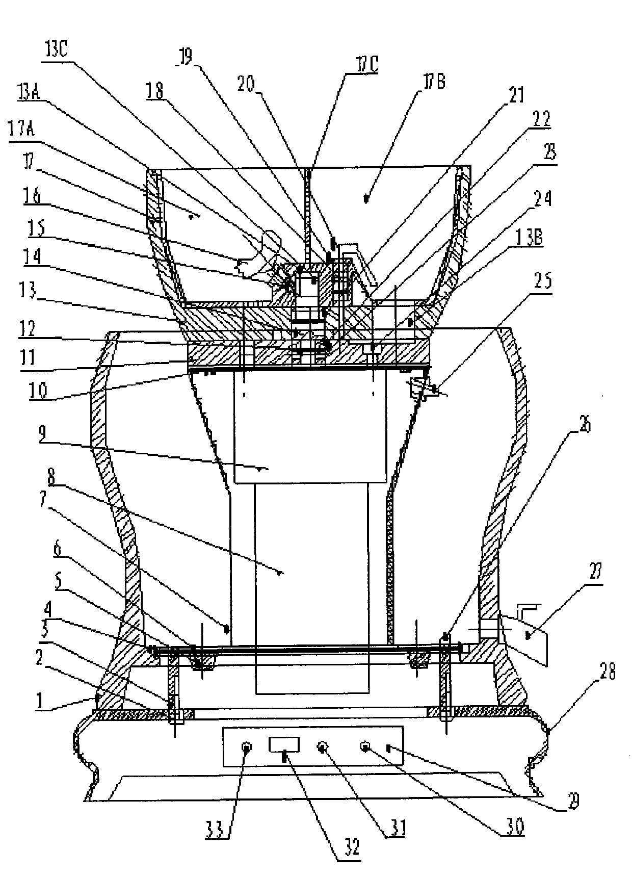
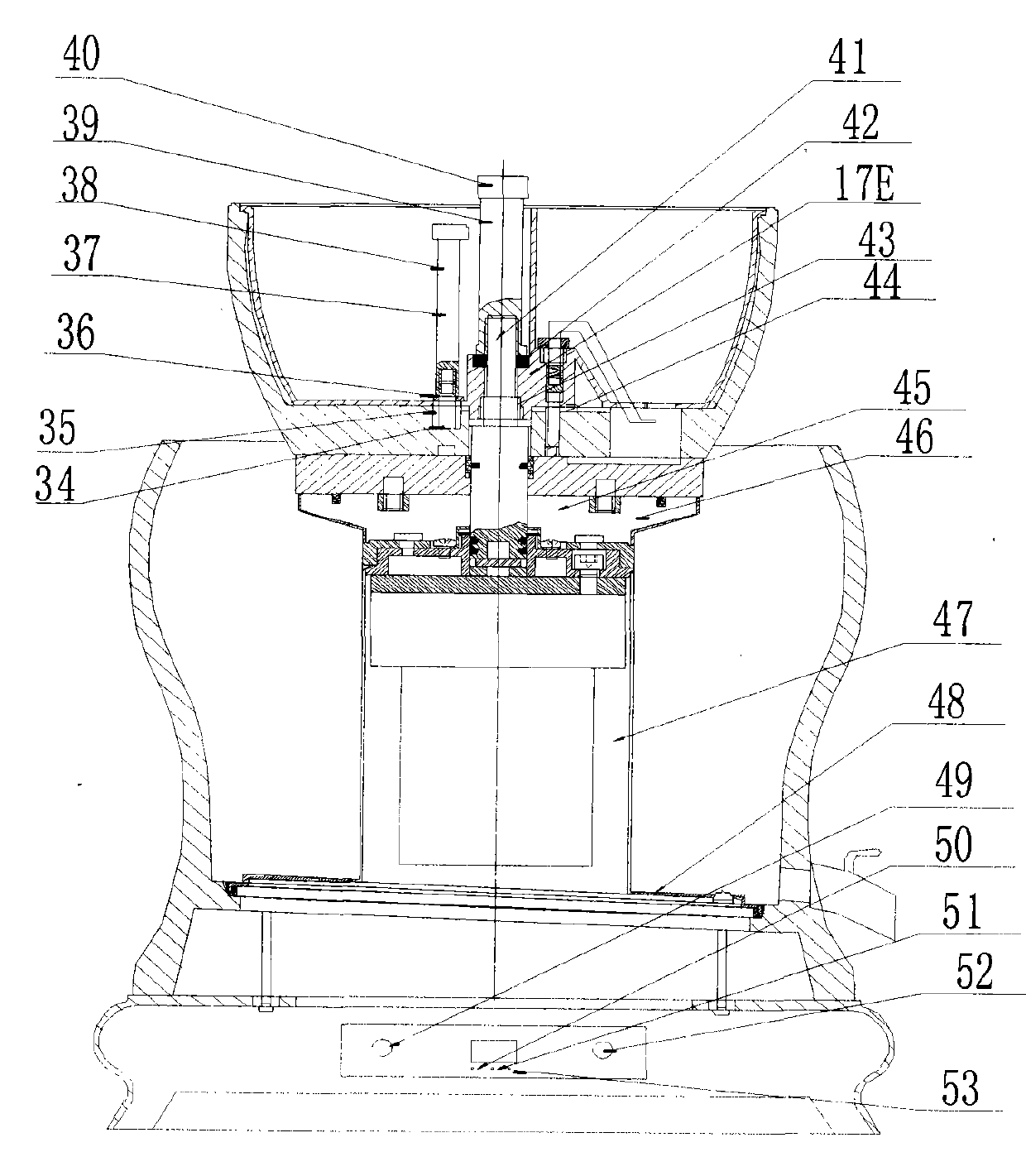
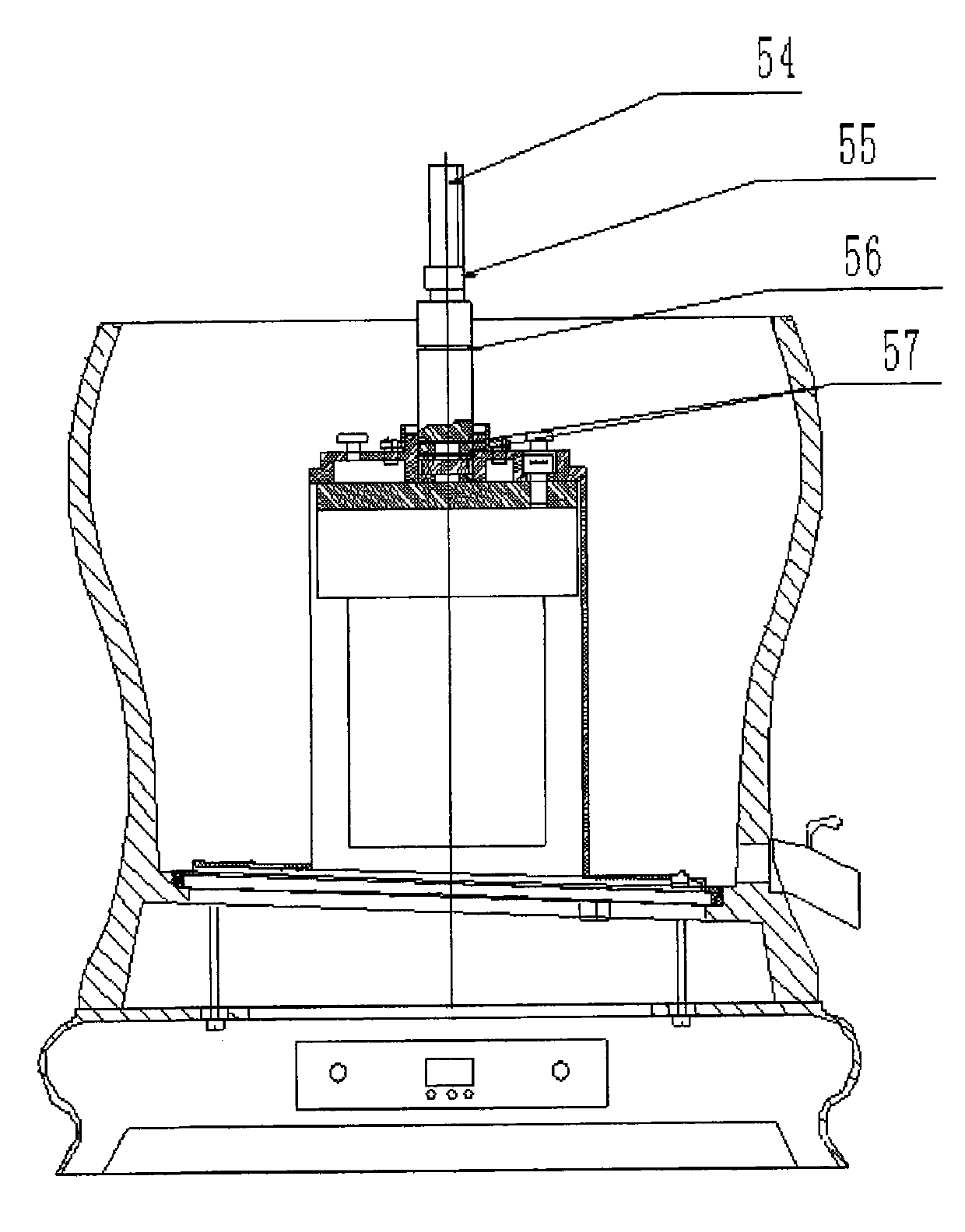
[0040] Below in conjunction with accompanying drawing, the present invention is explained in detail, figure 2 It is a front view of an improved automatic refiner structure of the present invention. image 3 is the central long axis structure diagram. Figure 4A It is the front view of the upper fastener structure. Figure 4B It is the side view of the upper fastener structure. Figure 5A It is the front view of the lower fastener structure. Figure 5B It is a top view of the lower fastener structure. Image 6 It is a diagram of the stirring rod device. Figure 7 Is the electric control schematic diagram.

[0041] As can be seen from the figure, an improved automatic refiner includes a slurry storage tank 1, a lower millstone pillar 7, an upper millstone 13, a slurry outlet 27, a base 28, a control circuit board 29, an electric motor 8, and a reduction box 9. Electric motor 8, reduction box 9, wherein, connecting rod shaft 14 is connected with upper grinding disc 13 by s...


PUM


Abstract

The present invention relates to an improved automatic slurry grinding machine, and belongs to food machinery. The improved automatic slurry grinding machine comprises a slurry storage tank 1, a lower grinding disc pillar 7, an upper grinding disc 13, a base 28 and the like, wherein the fastener coupling device 45 comprises an upper fastener 46 and a lower fastener 47, the lower fastener 47 comprises a lower fastener bracket 64, a lower fastener sleeve 65, a fastener nail 66, a sealing cover 68, a sealing ring 69, a reduction gearbox 9 and a motor 8, the water outlet gate device 38 comprises a water outlet gate screw 34, a water outlet gate hole 35, a water outlet gate rubber ring 36, an adjustment nut 37 and a water tank 44, the locking device 39 of the upper grinding disc 13 comprises a locking bolt 40, a central long shaft 41, a flat pad rubber ring 42 and an upper grinding disc inner hexagonal hole 43, and the stirring rod device 73 comprises a stirring rod horizontal handle 74 and a stirring rod long handle 75. According to the present invention, the upper grinding disc can be removed, such that human hands can directly insert into the slurry storage tank so as to clean; no slurry is remained on the bottom of the slurry storage tank; and the slurry is ensured, bottom pasting does not appear, and the beverage quality can be improved.

Description

technical field [0001] The invention relates to an improved automatic pulp refiner, which belongs to food machinery. Background technique [0002] In the food industry, an automatic refiner applied for and authorized by the applicant, (patent No. 201110101402.7) such as figure 1 Shown, comprise, storage tank 1, lower grinding disc pillar 7, upper grinding disc 13, slurry outlet 27, base 28, control circuit board 29, motor 8, reduction box 9, parts such as; Wherein, connecting rod shaft 14 is connected with thread The upper grinding disc 13 is connected; the upper grinding disc 13 is equipped with a material disc 17, a locking screw 16, a locking rubber sleeve 15, a spring 18, a spring nut 19, a movable rod 20, and a leveling rubber pad 21; the upper grinding disc 13 has a material hole 13B, Clean clear water and food raw materials, thus the material hole 13B enters the gap between the upper millstone 13 and the lower millstone 11; the opposite surface of the upper millstone...

Claims


Application Information

Patent Timeline
Patent Type & Authority Applications(China)
IPC IPC(8): B02C7/08B02C7/11B02C7/17B02C25/00
Inventor 文树雄黄启荣甘志毅文树明
Owner 文树雄
Why Eureka
Try Eureka