Concentric Flow Regulator

A flow regulator, concentric technology, applied in flow control, control/regulation systems, instruments, etc., can solve the problems of sample distortion, polluted water samples, etc., achieve high fidelity, improve fidelity, and convenient operation Effect

Inactive Publication Date: 2016-02-17
INST OF HYDROGEOLOGY & ENVIRONMENTAL GEOLOGY CHINESE ACAD OF GEOLOGICAL SCI
View PDF7 Cites 0 Cited by
  • Summary
  • Abstract
  • Description
  • Claims
  • Application Information

AI Technical Summary

Problems solved by technology

[0009] The purpose of the present invention is to provide a concentric flow regulator that does not change the shape of the streamline bundle of the water sample, so as to solve the problem that the sample is distorted due to the precipitation of volatile and semi-volatile substances in the polluted water sample caused by the deformation of the streamline bundle

Method used


Image

  • Concentric Flow Regulator
  • Concentric Flow Regulator
  • Concentric Flow Regulator

Examples


Embodiment Construction

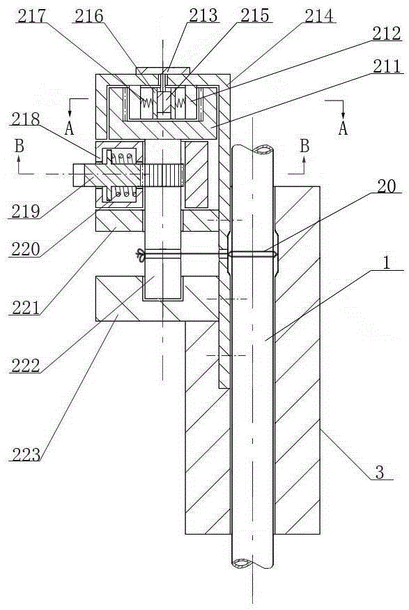
[0020] Such as figure 1 As shown, the concentric flow regulator of the present invention has an axial core hole in a straight handle-shaped handle 3, and the sampling hose 1 is threaded through the core hole, and the rod body of the handle 3 is provided with a core The horizontal rope hole interlinked by the holes is provided with a rotating shaft rope tightener winding a fastening rope at one end of the handle bar 3, and the fastening rope 20 pulled out from the rotating shaft rope tightener passes through the rope passing hole on the handle bar 3 and After passing through the core hole, its end is fixed on the rod body of the handle bar 3 .

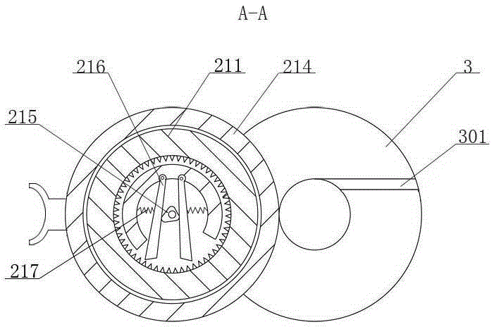
[0021] There are many ways to fix the end of the fastening rope 20. One is to open a slit 301 tangent to the edge of the core hole on the upper surface of the grip bar 3. The depth of the slit reaches the height of the rope hole, and the fastening The end of rope 20 is embedded and fixed in this slit 301 on the grip bar 3 ( figure 2 ...


PUM


Abstract

The invention relates to a concentric type flow regulator. The concentric type flow regulator is characterized in that an axial core hole and a transverse rope through hole are formed in a rod body of a holding rod, wherein a sampling hose penetrates through the axial core hole, and the transverse rope through hole is communicated with the core hole; a rotating shaft euphroe for winding a fastening rope is arranged at one end of the holding rod, the rope through hole is opposite to the rotating shaft euphroe, and after the fastening rope led out of the rotating shaft euphroe penetrates through the rope through hole and stretches into the core hole, the end of the fastening rope is fixed to the rod body of the holding rod; the fastening rope surrounds the sampling hose by a circle in the core hole, wherein the sampling hose penetrates through the core hole. The sampling hose can be regulated in a ring type packing mode through the fastening rope, the purpose of concentric type flow regulation is achieved, the streamline bundle of water which flows through the sampling hose is always kept cylindrical, and therefore the probability of separating out volatile and semi-volatile materials in a polluted water sample is reduced, and the fidelity degree of the sample is increased.

Description

technical field [0001] The invention relates to a flow regulating device, in particular to a concentric flow regulator. Background technique [0002] At present, the adjustment methods of liquid flow mainly include contact flow adjustment and non-contact flow adjustment. [0003] Contact flow adjustment, such as various valves, the flow adjustment device is in direct contact with the liquid, and the quality of the liquid flowing through it is easily affected by the flow adjustment device; on the other hand, the streamline bundle of the liquid entering and leaving the flow adjustment device changes greatly. It cannot meet the requirements for flow adjustment when collecting samples containing volatile and semi-volatile substances that require stable liquid streamline bundles. [0004] Non-contact flow regulation is to control the flow by changing the pipe diameter of the pipeline that transports the liquid. The common way is "squeezing", such as various pipe clamps, and the ...

Claims


Application Information

Patent Timeline
Patent Type & Authority Patents(China)
IPC IPC(8): G05D7/00
Inventor 温吉利温馨王翠玲张云杨柳
Owner INST OF HYDROGEOLOGY & ENVIRONMENTAL GEOLOGY CHINESE ACAD OF GEOLOGICAL SCI
Why Eureka
Try Eureka