Method and apparatus for determining the angle of a movable member

A component and angle technology, applied in the directions of positioning, utilization of re-radiation, reflection/re-radiation of radio waves, etc., can solve the problems of lack of possibility of sensor system construction, and achieve high robustness, robustness convenience, high robustness and The effect of precision

Inactive Publication Date: 2016-12-14
SIEMENS AG
View PDF5 Cites 0 Cited by
  • Summary
  • Abstract
  • Description
  • Claims
  • Application Information

AI Technical Summary

Problems solved by technology

But these methods have only strongly restricted application in harsh industrial environments
Many of these methods cannot be applied to an adequate degree in dirty, wet and highly vibrating environments
Often there is also a lack of structural possibilities for placing corresponding angle-determining sensor systems

Method used


Image

  • Method and apparatus for determining the angle of a movable member
  • Method and apparatus for determining the angle of a movable member
  • Method and apparatus for determining the angle of a movable member

Examples


Embodiment Construction

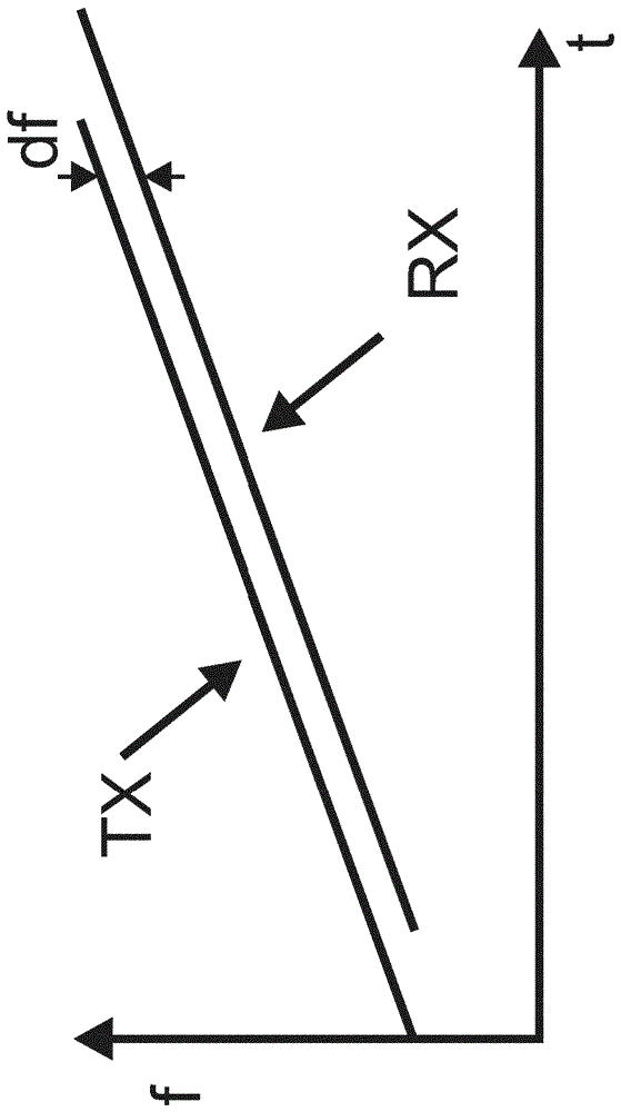
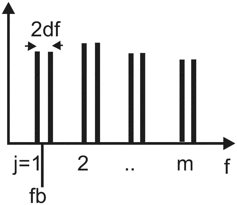
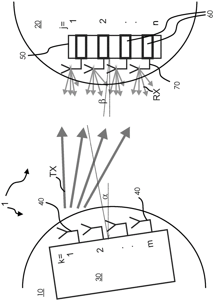
[0040] exist figure 1 The device according to the invention shown in FIG. 2 comprises a first component 10 of a plant 1 according to the invention and a second component 20 which is movable relative thereto. In the exemplary embodiment shown, the first component 10 and the second component 20 are each arranged rotatably movable relative to a virtual connection line between the first component 10 and the second component 20 (otherwise corresponding to the illustrated In a not specifically shown embodiment of an embodiment, the first component 10 is arranged rotatably, while the second component 10 is positioned in a rotationally fixed manner, or the second component 20 is arranged rotatably while the first component 10 is rotationally fixed ground; in addition, the first and second members may also be additionally translatable relative to each other in other embodiments).

[0041] A multi-channel radar sensor 30 with m channels, that is to say with m sensor antennas 40 , which...


PUM


Abstract

For determining the angle between a first member (10) and a second member (20) movable relative to the first member ( In the case of the method α+β), a radar sensor (30) is used which has at least two channels (40) arranged kinematically coupled to the first component and spaced apart from each other, and at least two channels (40) are used coded radar targets ( 60 ) which are each arranged kinematically coupled to the second component ( 20 ) and are spatially spaced apart from each other, wherein in this method each one of the at least two channels ( 40 ) of the radar sensor is used sending a signal (TX) to each of the radar targets (60), wherein by means of the radar target (60) respectively transmitting at least one coded signal (RX) upon or after receiving such a signal (TS), at least two of which Each of the coded signals (RX) is received by means of one or more channels (40) of the radar sensor, and a time relationship between at least two of the received coded signals (RX) is determined and is considered for determining the angle (α+β).

Description

technical field [0001] The invention relates to a method and a device for determining the angle of a movable component. Background technique [0002] It is often necessary in the case of plants or installations with components that are movable relative to each other to obtain relative position or angle information between these movable components. For example, it is of interest in the process to determine the angular position of the swivel bracket supporting the axle relative to the vehicle body. [0003] Methods based on optical methods for determining angles by means of automatic synchronization transmitters (Drehgebern) are known. Likewise, methods are known that use a resistive layer to determine the angular proportional length of the intercepted arc. Inertia-based angle determination methods are known from military technology. However, these methods can only be used to a very limited extent in harsh industrial environments. Many of these methods cannot be applied to...

Claims


Application Information

Patent Timeline
Patent Type & Authority Patents(China)
IPC IPC(8): G01S13/75G01S13/87G01S7/02G01S7/40G01S5/02G06F3/0346
CPCG01S7/025G01S7/4026G01S13/751G01S13/753G01S13/755G01S13/874G01S7/403G01S7/4034G01S13/02
Inventor J.许特纳A.齐洛夫
Owner SIEMENS AG
Why Eureka
Try Eureka