Single-degree-of-freedom joint mechanical driven by two pneumatic artificial muscle assemblies

A pneumatic artificial muscle and degree of freedom technology, applied in the field of bionic robots, can solve the problems of not being able to simulate the flexibility of biological muscles well, the overall weight of the robot is high, and the bionic effect is poor, so as to achieve outstanding bionic features, reduce the weight of joint structures, and improve The effect of flexibility

Inactive Publication Date: 2014-07-02
SHANGHAI UNIV
View PDF6 Cites 19 Cited by
  • Summary
  • Abstract
  • Description
  • Claims
  • Application Information

AI Technical Summary

Problems solved by technology

[0003] Analyzing the motion drive mode of bionic robots, most of them are driven by motors at present. The motor drive mode has the advantages of relatively simple control and accurate position and speed control. However, since the motor is a rigid component, it cannot simulate the flexibility of biological muscles well. Problems such as poor bionic effect and high overall weight of the robot

Method used


Image

  • Single-degree-of-freedom joint mechanical driven by two pneumatic artificial muscle assemblies
  • Single-degree-of-freedom joint mechanical driven by two pneumatic artificial muscle assemblies

Examples


Embodiment 1

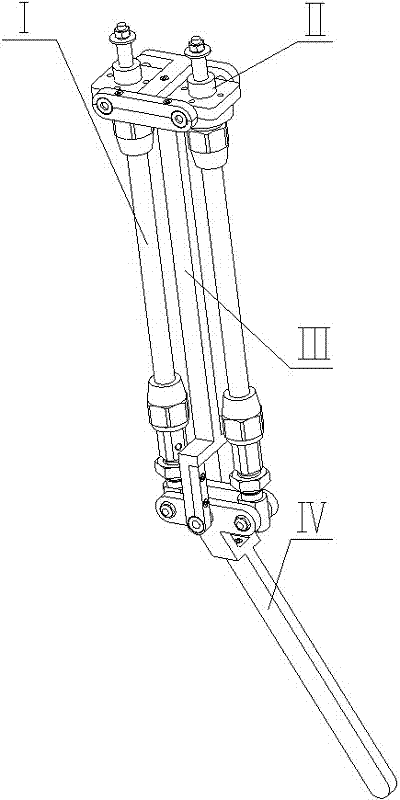
[0016] Such as Figure 1~Figure 2 As shown, the single-degree-of-freedom joint mechanism driven by dual pneumatic artificial muscles includes two pneumatic artificial muscle components (Ⅰ), two rotating parts (II), a thigh skeleton (Ⅲ) and a calf skeleton (Ⅳ). The two pneumatic artificial muscle components (I) are arranged in parallel on both sides of the thigh frame (III), and the upper ends of the two pneumatic artificial muscle components (I) are connected to the two rotating parts (II) respectively, and The lower ends are rotatably connected with the lower leg frame (Ⅳ); the thigh frame (Ⅲ) includes an "I"-shaped piece (12), a rectangular strip (13) and a fork (14), and the rectangular strip (13 ) are respectively fixed and connected with the "I"-shaped piece (12) and the fork-shaped piece (14) by screws; The skeleton (15) and the lower leg skeleton (16) are fixedly connected by screws; the fork (14) of the thigh skeleton (Ⅲ) is connected to the lower leg of the lower leg...

Embodiment 2

[0018] This embodiment is basically the same as Embodiment 1, and the special features are as follows:

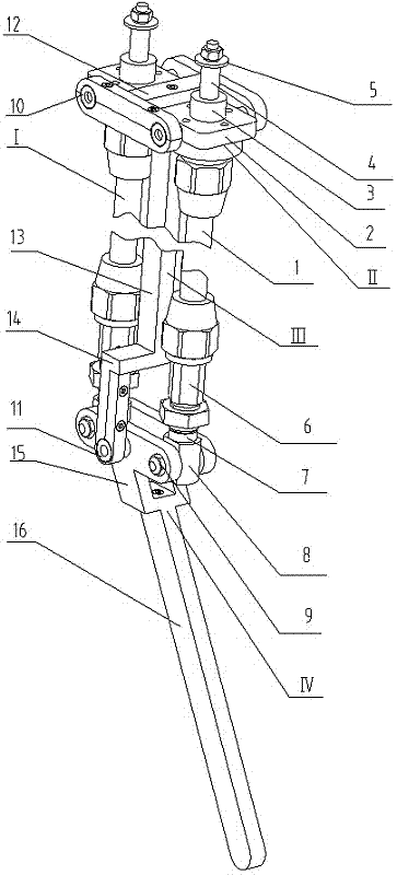
[0019] The pneumatic artificial muscle assembly (I) includes a pneumatic artificial muscle (1), a moving pair connector (4), a trachea joint (6), a round nut (7), a rotating pair connector (8) and a large washer (5 ), the two ends of the pneumatic artificial muscle (1) are fixedly connected with the moving pair connector (4) and the trachea joint (6) through threads; the rotating pair connector (8) and the trachea connector (6) are threaded Fixed connection; the rotating pair connecting piece (8) forms a rotating pair with the lower leg upper frame (15) through the pin shaft (9); the large washer (5) is fixed on the moving pair connecting piece (4) by using a nut and a spring washer ; The axial assembly length of the pneumatic artificial muscle assembly (I) can be fine-tuned through the round nut (7).

[0020] The rotating part (II) includes a bearing connecting part (2) a...


PUM


Abstract

The invention relates to a single-degree-of-freedom joint mechanical driven by two pneumatic artificial muscle assemblies, and belongs to the technical field of bio-robots. The single-degree-of-freedom joint mechanical driven by the two pneumatic artificial muscle assemblies can be used in leg joints of the four-footed bio-robots. The single-degree-of-freedom joint mechanical driven by the two pneumatic artificial muscle assemblies comprises the two pneumatic artificial muscle assemblies, two rotary parts, a thigh framework and a crus framework, wherein the two ends of the two pneumatic artificial muscle assemblies are connected with the rotary parts and pin shafts. The single-degree-of-freedom joint mechanical driven by the two pneumatic artificial muscle assemblies has the bionic advantages of being large in movement range, high in movement speed, good in flexibility and the like.

Description

technical field [0001] The invention relates to a single-degree-of-freedom joint mechanism driven by dual pneumatic artificial muscles, which can be used for the leg joints of quadruped bionic robots, belongs to the technical field of bionic robots, and has the advantages of large joint motion range, fast motion speed, and good flexibility. Background technique [0002] With the deepening of bionic robot research, research hotspots have expanded from robot walking to high-speed motion (such as jumping and running). The high-speed movement of the robot can greatly improve the mobility of the robot, allowing the robot to overcome obstacles. This puts forward higher requirements for the robot mechanism design. [0003] Analyzing the motion drive mode of bionic robots, most of them are driven by motors at present. The motor drive mode has the advantages of relatively simple control and accurate position and speed control. However, since the motor is a rigid component, it cannot...

Claims


Application Information

Patent Timeline
Patent Type & Authority Applications(China)
IPC IPC(8): B25J17/00
Inventor 雷静桃吴建东戴文杰
Owner SHANGHAI UNIV
Why Eureka
Try Eureka