A Dynamic Positioning Method for Optimal Angle of Attack Frame of Aircraft HUD

A technology of dynamic positioning and angle of attack, applied in directions such as aircraft landers

Active Publication Date: 2016-06-08
沈阳飞机设计研究所扬州协同创新研究院有限公司
View PDF5 Cites 0 Cited by
  • Summary
  • Abstract
  • Description
  • Claims
  • Application Information

AI Technical Summary

Problems solved by technology

But when the optimal true angle of attack changes dynamically, it is no longer applicable

Method used


Image

  • A Dynamic Positioning Method for Optimal Angle of Attack Frame of Aircraft HUD
  • A Dynamic Positioning Method for Optimal Angle of Attack Frame of Aircraft HUD
  • A Dynamic Positioning Method for Optimal Angle of Attack Frame of Aircraft HUD

Examples


Embodiment Construction

[0025] The present invention will be further described in detail below through specific embodiments in conjunction with the accompanying drawings.

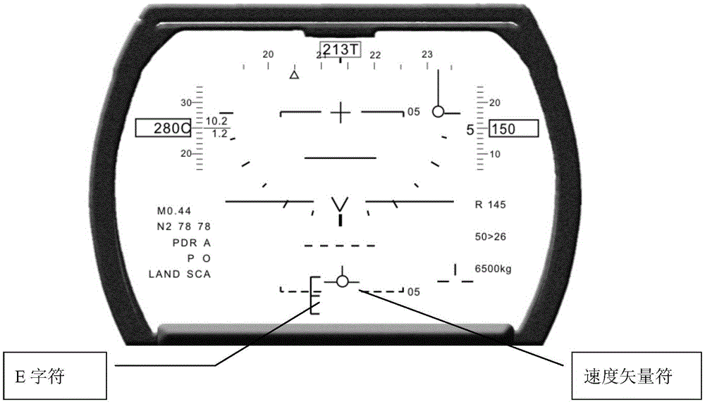
[0026] Step 1: Calculate the angle of attack α corresponding to the center of the "E symbol" E :

[0027] Let the predicted inertial angle of attack read from the inertial navigation α P =3°

[0028] Inertial sideslip angle β I =1°

[0029] Aircraft roll angle γ=0°

[0030] The true angle of attack α read from the air data system t = 2°

[0031] The angle of attack α corresponding to the center of the "E symbol" can be calculated E :

[0032] α E =11+α P -α t +β I tgγ=12°

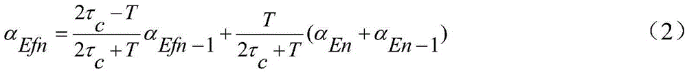
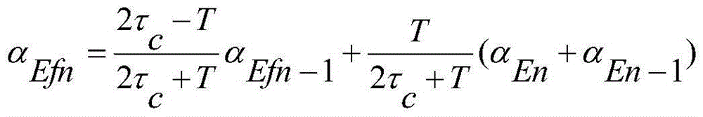
[0033] Step 2: Correspond to the angle of attack α to the center of the "E symbol" E Filtering:

[0034] Constant τ c = 0.3, T = 0.05

[0035] When n=0, α Ef0 =11°, α E0 = 11°,

[0036] Calculate α when n=1 Ef1

[0037] α Efn = 2 τ c - T 2 τ c + T α Efn - 1 + T 2 τ c + T ( α En + α En...


PUM


Abstract

The invention provides an aircraft head-up display attack angle frame dynamic positioning method and belongs to an airborne avionic system. The method is characterized by comprising the following steps: reading a predicated inertia attack angle alpha P, a predicated inertia sideslip angle beta I and a predicated aircraft roll angle gamma which are given out by an inertial navigator, as well as a real attack angle alpha t given out by an air data system, and calculating a corresponding attack angle alpha E of an 'E symbol' center; filtering the 'E symbol' center alpha E; displaying an optimal attack angle frame on a head-up display according to the value of the filtered alpha E by virtue of a display control system. When the method is used for performing dynamic positioning on the optimal attack angle frame, the optimal attack angle frame can be cooperated with a dynamic speed vector symbol so as to ensure that an aircraft lands along a standard glide slope.

Description

Technical field [0001] The invention belongs to an airborne avionics system, and particularly relates to a dynamic positioning method for an aircraft head-up display of the best angle of attack frame. Background technique [0002] The best angle of attack frame (also known as the "E" character) is displayed on the HUD, and is used in conjunction with the speed vector symbol (the pilot controls the aircraft so that the speed vector symbol is within the best angle of attack frame), which can assist the pilot in landing Maintain the aircraft's best angle of attack and fly along the standard landing glideslope to ensure a safe and accurate landing of the aircraft. [0003] In the prior art, the display position of the best angle of attack frame on the head-up display is fixed. But when the best true angle of attack changes dynamically, it is no longer applicable. This is because the speed vector symbol is driven by the accelerated inertial angle of attack and sideslip angle, while th...

Claims


Application Information

Patent Timeline
Patent Type & Authority Patents(China)
IPC IPC(8): B64D45/04
Inventor 路志伟姚丽君季强何枫
Owner 沈阳飞机设计研究所扬州协同创新研究院有限公司
Why Eureka
Try Eureka