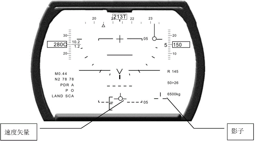
Method for positioning virtual velocity vector symbol of head up display of airplane

A symbol and head-up display technology, applied in speed/acceleration/shock measurement, speed/acceleration/electric shock meter details, measuring devices, etc., can solve the problem of not knowing the direction of aircraft speed, and the best angle of attack for speed vector sign alignment frame difficulty

Active Publication Date: 2014-08-13
沈阳飞机设计研究所扬州协同创新研究院有限公司
View PDF5 Cites 2 Cited by
  • Summary
  • Abstract
  • Description
  • Claims
  • Application Information

AI Technical Summary

Problems solved by technology

The best angle of attack box is displayed in the middle of the HUD, so it is very difficult to align the best angle of attack box with the velocity vector symbol
In order to solve this problem, the speed vector symbol is displayed within ±2°, but it will bring another problem: the pilot cannot know the true speed direction of the aircraft

Method used


Image

  • Method for positioning virtual velocity vector symbol of head up display of airplane
  • Method for positioning virtual velocity vector symbol of head up display of airplane

Examples


Embodiment Construction

[0018] The present invention will be described in further detail below through specific embodiments and in conjunction with the accompanying drawings.

[0019] Step 1: Determine the pitch angle of the "shadow" symbol

[0020] Let the predicted inertial angle of attack α read from the inertial navigation P = 3°

[0021] Then the pitch angle of the "shadow" symbol: E L =-α p = -3°

[0022] Step 2: Determine the azimuth of the "shadow" symbol

[0023] Let the inertial sideslip angle β read from the inertial navigation I = 1°

[0024] Then the "shadow" symbol azimuth A Z = 1°

[0025] Step 3: Determine when to display

[0026] due to beta I =1°, at this time the "shadow" is not displayed.

[0027] When repeating the above steps, if the inertial sideslip angle β read from the inertial navigation I =3°︱β I ︱>2°, the "shadow" symbol will be displayed at this time.


PUM


Abstract

The invention discloses a method for positioning and calculating a virtual velocity vector symbol of head up display of an airplane and belongs to onboard avionics systems. The method is characterized in that a predicted inertia attack angle alpha[p] obtained through inertial navigation output is read and the pitch angle of the shadow symbol is determined; an inertia sideslip angle beta [I] obtained through inertial navigation output is read, and the azimuth angle of the shadow symbol is determined; the display time of the shadow symbol is determined. According to the method, display of the virtual velocity vector symbol of the airplane is reliably and accurately positioned and calculated and the method can be coordinated with optimal attack angle frame dynamic positioning and guarantee that the airplane is landed along a standard glide slope.

Description

technical field [0001] The invention belongs to an airborne avionics system, in particular to a method for locating a virtual velocity vector symbol on an aircraft head-up display. Background technique [0002] A virtual speed vector symbol (also known as a "shadow") is displayed on the HUD and is used in conjunction with the speed vector symbol. The speed vector symbol is driven by the inertial angle of attack and inertial sideslip angle. If the crosswind in the air is relatively strong during landing, the aircraft’s inertial sideslip angle will also be large, and the speed vector symbol will shift to the edge of the HUD. However, the optimal angle of attack frame is displayed in the middle of the HUD, so it is very difficult to align the optimal angle of attack frame with the velocity vector symbol. In order to solve this problem, the speed vector symbol is displayed within ±2°, but it will bring another problem: the pilot cannot know the real speed direction of the aircr...

Claims


Application Information

Patent Timeline
Patent Type & Authority Applications(China)
IPC IPC(8): G01P1/07G01D7/06
Inventor 路志伟季强杨敏李晓峰
Owner 沈阳飞机设计研究所扬州协同创新研究院有限公司
Why Eureka
Try Eureka