
Anti-vibration device

A technology for anti-vibration devices and components, applied in the direction of non-rotational vibration suppression, springs made of plastic materials, springs, etc., can solve problems such as increasing the spring constant, and achieve the effect of increasing the spring constant and reducing the spring constant

Inactive Publication Date: 2016-08-24
TOYO TIRE & RUBBER CO LTD
View PDF9 Cites 1 Cited by
  • Summary
  • Abstract
  • Description
  • Claims
  • Application Information

AI Technical Summary

Problems solved by technology

[0009] However, in the conventional anti-vibration bushing 101 described above, there is a problem that it is not possible to sufficiently increase the spring constant in the axial direction while reducing the spring constant in the torsional direction and the spring constant in the vertical direction to the shaft. at this point

Method used


Image

  • Anti-vibration device
  • Anti-vibration device
  • Anti-vibration device

Examples


no. 1 approach

[0140] refer to Figure 14 and Figure 15 , the method of assembling the anti-vibration device 400 assembled from the vulcanized molded body D and the cylindrical member 440 will be described. In the first embodiment (anti-vibration device 100), by rubber matrix compression process (cf. Figure 7 ) to compress the rubber base 30 (the first rubber part 31 and the second rubber part 32 ) in the direction of the axis O, but the rubber base compression process is omitted in the fourth embodiment (the anti-vibration device 400 ).

[0141] Figure 14 (a) is a cross-sectional view of the vulcanized molded body D in a state before drawing in the outer cylinder drawing process; Figure 14 (b) is a cross-sectional view of the vulcanized molded body D in a state where drawing has been performed in the outer cylinder drawing process.

[0142] Such as Figure 14 As shown, for the vulcanized molded body D, in the outer cylinder drawing process, the diameters of the first outer cylinder...


PUM


Abstract

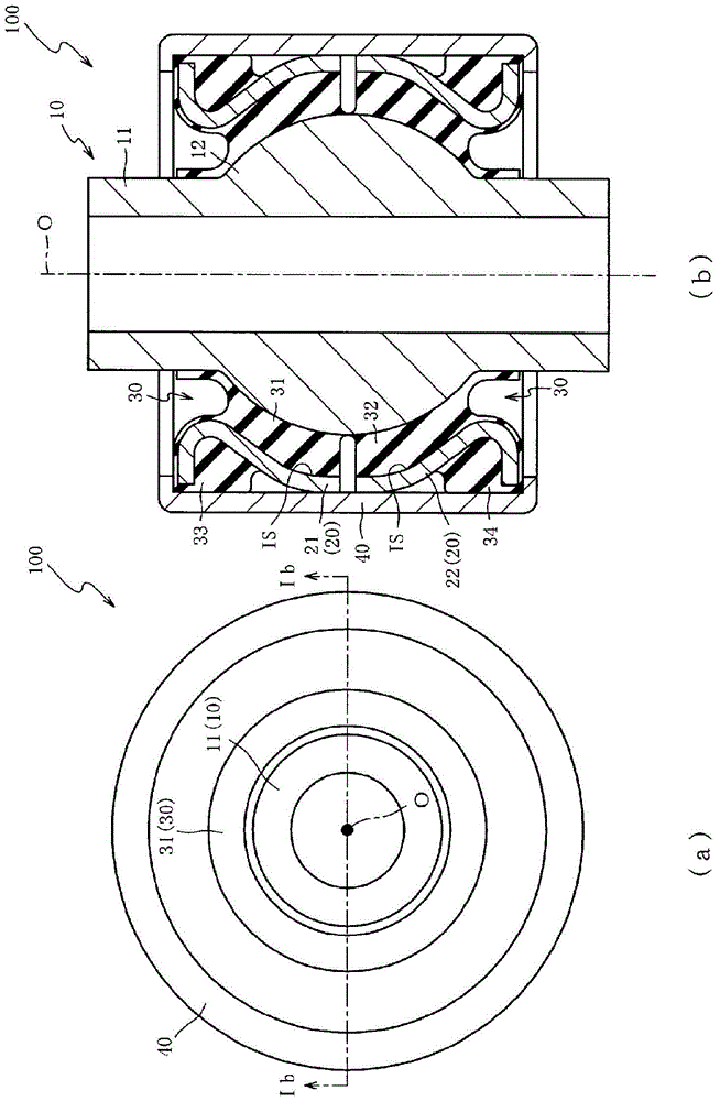
The present invention provides an anti-vibration device capable of increasing the spring constant in the axial direction while reducing the spring constant in the torsional direction and the spring constant in the axial perpendicular direction. In the state where the dividing surface of the first rubber part (431) and the dividing surface of the second rubber part (432) are separated in the axis (O) direction and a space (SP) is formed between the dividing surfaces, the cylinder A shape member (440) is used to hold and fix the first outer cylinder part (421) and the second outer cylinder part (422). Through the space (SP) between the dividing surface of the first rubber part (431) and the dividing surface of the second rubber part (432), it is possible to suppress the shear component of the rubber matrix (430) in the torsional direction and While the compression component of the rubber matrix (430) in the direction perpendicular to the axis (O) is ensured, the compression component of the rubber matrix (430) in the direction of the axis (O) is ensured. As a result, the spring constant in the torsional direction and the spring constant in the direction perpendicular to the axis (O) can be reduced, and the spring constant in the axis (O) direction can be increased.

Description

technical field [0001] The invention relates to an anti-vibration device, in particular to an anti-vibration device capable of increasing the spring constant in the axial direction while reducing the spring constant in the torsional direction and the spring constant in the vertical direction of the shaft. Background technique [0002] In a bush (anti-vibration device) used in a suspension device that connects an inner cylinder member and an outer cylinder member with a rubber matrix composed of a rubber-like elastic body, it is required to reduce the spring constant in the torsional direction in order to ensure The ride comfort of the car. [0003] Patent Document 1 discloses an anti-vibration bushing 101 (vibration-proof device) in which a radially outwardly protruding bushing is provided at the axially middle portion of the inner cylinder 1 (inner cylinder member) in order to reduce the spring constant in the torsional direction. The spherical protruding portion 4 is form...

Claims


Application Information

Patent Timeline
Patent Type & Authority Patents(China)
IPC IPC(8): F16F1/38F16F15/08
CPCF16F1/3807F16F1/3863F16F1/38F16F1/3828F16F15/08
Inventor 信夫俊一古泽纪光
Owner TOYO TIRE & RUBBER CO LTD
Learn More