Installation structure of sound shield
A sound-proof cover and sound-proof technology, applied in the direction of engine components, machines/engines, mechanical equipment, etc., can solve problems such as vibration reduction performance deterioration, and achieve the effect of preventing performance deterioration and vibration reduction.
- Summary
- Abstract
- Description
- Claims
- Application Information
AI Technical Summary
Problems solved by technology
Method used
Image
Examples
no. 1 Embodiment approach
[0037] (The structure of the installation structure of the sound insulation cover)
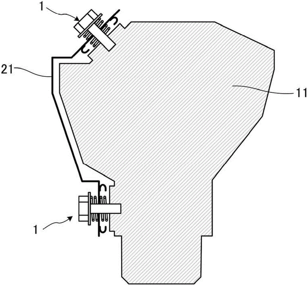
[0038] The installation structure (installation structure) of the sound insulation cover according to the first embodiment of the present invention is as follows: figure 1 As shown, a sound shield 21 provided near the engine 11 which is a noise source that vibrates and generates noise is attached to the engine 11 via springs. It should be noted that the noise generation source is not limited to the engine 11, and may be an oil pan, an exhaust pipe, or the like. The sound shield 21 is attached to the engine 11 through the attachment structure 1 and covers a part of the engine 11 . It should be noted that the sound shielding cover 21 is not limited to cover a part of the noise generation source, and may cover the whole.
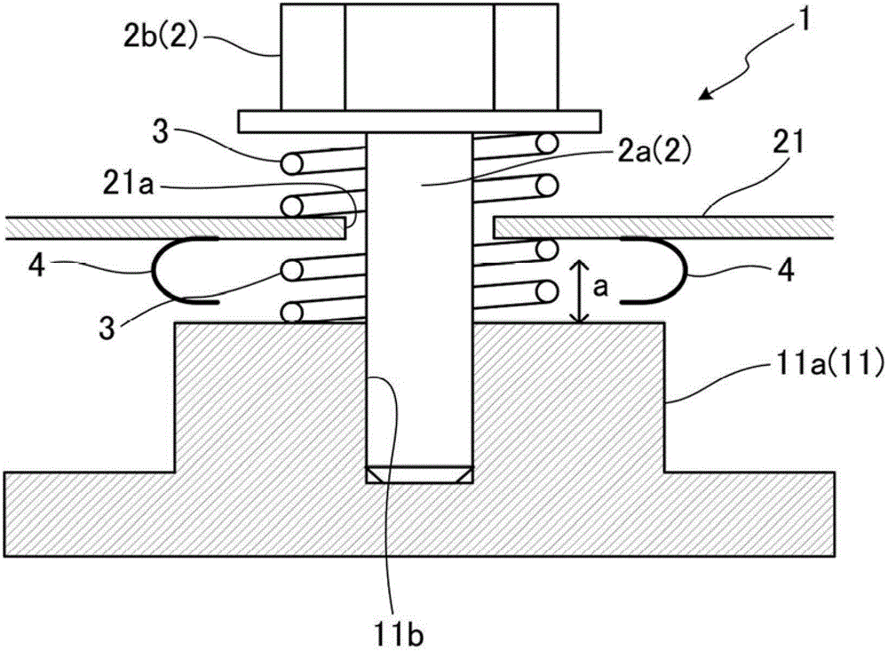
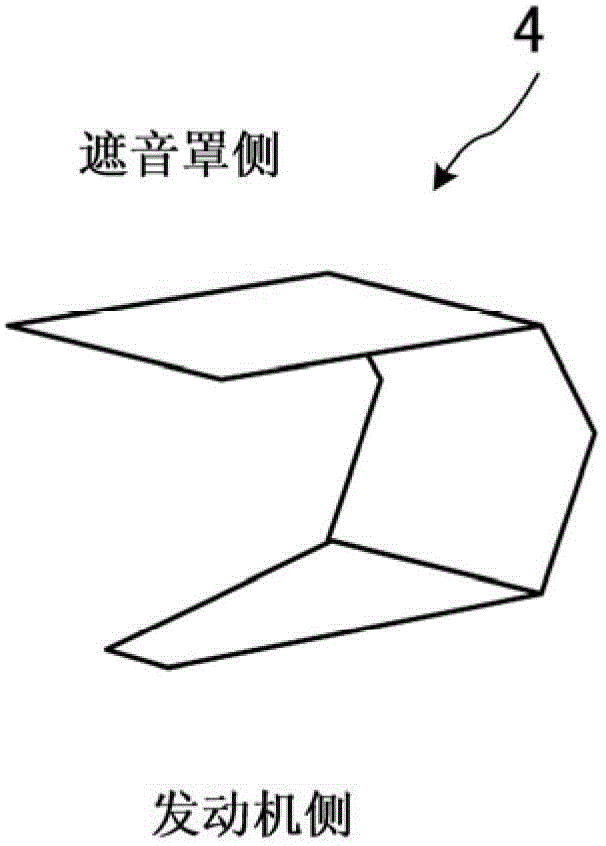
[0039] Installation configuration 1 such as figure 2 As shown, it has: a bolt (joint member) 2; a pair of springs 3, 3; and an abutment spring 4. The bolt 2 has a male thr...
no. 2 Embodiment approach
[0051] (The structure of the installation structure of the sound insulation cover)
[0052] Next, an attachment structure 201 according to a second embodiment of the present invention will be described. It should be noted that the same reference numerals are attached to the same components as those described above, and their descriptions will be omitted. The installation structure 201 of this embodiment differs from the installation structure 1 of the first embodiment in that, as Figure 5 As shown, the abutment spring 204 is formed by cutting a part of the sound shield 21 .
[0053] as top view Figure 6 As shown, in the vicinity of the opening 21a of the sound insulating cover 21, a part of the sound insulating cover 21 is cut at intervals of 90° with the opening 21a as the center, and the cut parts are respectively bent into an L-shaped cross section. This forms four abutment springs 204 on the sound shield 21 . According to such a configuration, it is not necessary to ...
PUM
 Abstract
Description
Claims
Application Information
 - R&D
- Intellectual Property
- Life Sciences
- Materials
- Tech Scout
- Unparalleled Data Quality
- Higher Quality Content
- 60% Fewer Hallucinations
Browse by: Latest US Patents, China's latest patents, Technical Efficacy Thesaurus, Application Domain, Technology Topic, Popular Technical Reports.
© 2025 PatSnap. All rights reserved.Legal|Privacy policy|Modern Slavery Act Transparency Statement|Sitemap|About US| Contact US: help@patsnap.com


