
Improved electric stapler

A stapler and electric technology, which is applied in the mechanical field, can solve the problems of inconvenience and inability of the stapler to work, and achieve the effect of reducing the number of staples and making it easy to take out paper

Inactive Publication Date: 2014-09-03
SUNWOOD HLDG GROUP
View PDF7 Cites 0 Cited by
  • Summary
  • Abstract
  • Description
  • Claims
  • Application Information

AI Technical Summary

Problems solved by technology

[0005] When this type of stapler needs to bind paper, it needs to overcome the force of the tension spring and the spring to push the paper into the paper opening. When the amount of paper is small, it is very inconvenient to push the paper into the paper opening due to the soft texture of the paper. There is a problem that the stapler cannot work when the amount of paper is low

Method used


Image

  • Improved electric stapler
  • Improved electric stapler
  • Improved electric stapler

Examples


Embodiment Construction

[0032] The following are specific embodiments of the present invention and the accompanying drawings to further describe the technical solutions of the present invention, but the present invention is not limited to these embodiments.

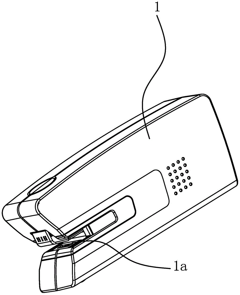
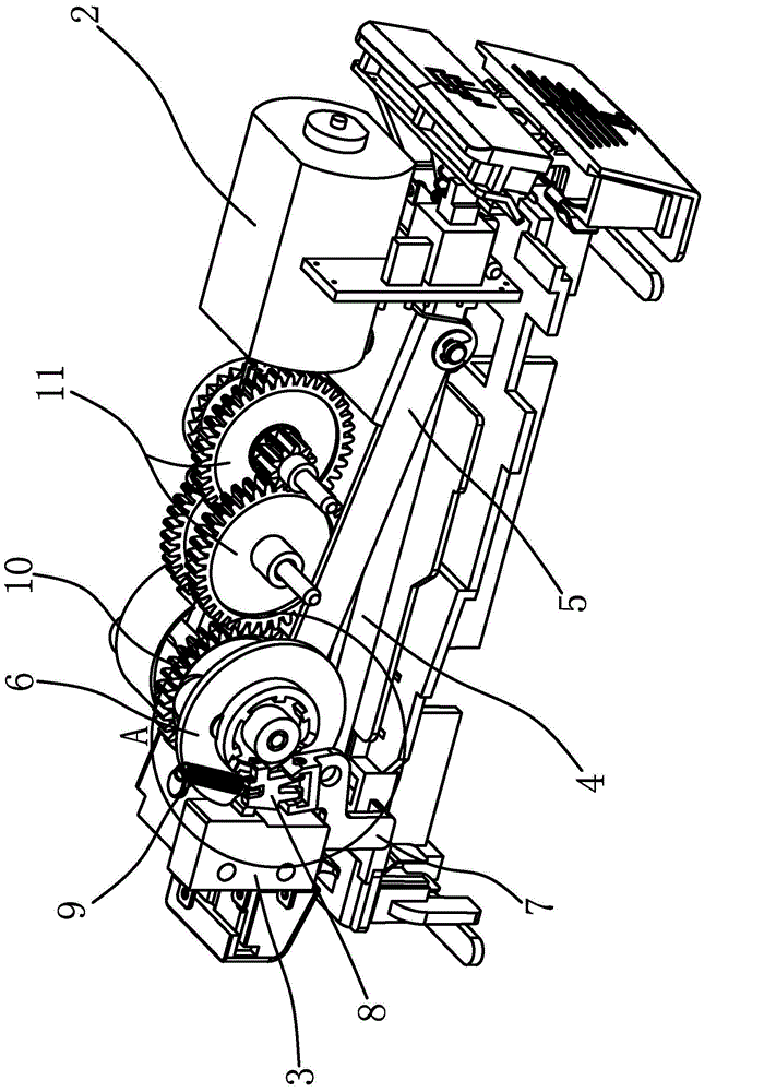
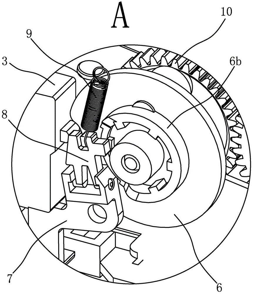
[0033] like figure 1 and figure 2 and image 3 As shown in the figure, the improved electric stapler includes a casing 1 with a cavity inside, the front end of the casing 1 is provided with a paper opening 1a, and the casing 1 is provided with a motor 2, a micro switch 3, a nail path 4 and a knife Frame 5, a drive gear 10 and a runner 6 driven by the drive gear 10 are arranged between the motor 2 and the micro switch 3. The outer edge of the runner 6 has a notch 6a, and a switch 7 is hinged on the inner wall of the housing 1. The switch The upper end of 7 is hinged with a paddle 8, one side of paddle 8 is in contact with the button of micro switch 3, a spring 9 is connected between paddle 8 and the inner wall of housing 1, and the wheel 6 is ...


PUM


Abstract

The invention provides an improved electric stapler, belonging to the machinery technology field. The improved electric stapler solves the problem that an existing electric stapler cannot work when less paper exists. The improved electric stapler comprises a shell with a hollow cavity, wherein the front end of the shell is provided with a paper inlet, a motor, a microswitch, a nail passage and a knife rest are arranged in the shell, a driving gear and a rotating wheel driven by the driving gear are arranged between the motor and the microswitch, the outer edge of the rotating wheel is provided with a recess, a switch is articulated on the inner side wall of the shell, the upper end of the switch is articulated with a shifting piece, one side of the shifting piece pushes against a button of the microswitch, a spring is connected between the shifting piece and the inner shell of the shell, the rotating wheel is arranged at one side of the switch and one side, opposite to the switch, of the rotating wheel is provided with a boss, a notch is formed in the boss, and the rotating wheel is rotated until the button of the microswitch is located at the recess, part of the switch is located in the notch. The improved electric stapler has the advantage of having capability of reducing the binding quantity.

Description

technical field [0001] The invention belongs to the technical field of machinery, and relates to an electric stapler, in particular to an improved electric stapler. Background technique [0002] Every office has at least one stapler, which provides us with an ideal means of binding many pages together for preservation. I believe that many students also have staplers at home. The stapler binds the paper, which is impossible or impossible. One of the missing office supplies. [0003] Staplers are generally divided into manual staplers and electric staplers. With the development of society and the advancement of science and technology, manual staplers can no longer meet people's needs. After people's improvement, electric staplers appear on the market. , This kind of stapler, just push the paper into the paper inlet of the stapler to complete the binding work. [0004] For example, the applicant previously disclosed an electric stapler [Application No.: 201320529107.6; Author...

Claims


Application Information

Patent Timeline
IPC IPC(8): B25C5/15B25C7/00
Inventor 林夏森
Owner SUNWOOD HLDG GROUP
Learn More