An energy storage and drive device applicable to hybrid electric vehicles

A technology for hybrid electric vehicles and drive devices, which is applied to hybrid electric vehicles, power plants, pneumatic power plants, etc., can solve the driving conditions of feedback energy and the efficiency of the reuse process of motor and battery state limitation and braking energy feedback It is not high, and it is difficult for the battery to achieve high-power charging in a short time, so as to achieve the effect of improving power performance and fuel economy, low quality, and low equipment power.

Active Publication Date: 2016-09-28
CHANGZHOU HAIKE NEW ENERGY TECH
View PDF8 Cites 0 Cited by
  • Summary
  • Abstract
  • Description
  • Claims
  • Application Information

AI Technical Summary

Problems solved by technology

[0006] However, the current braking energy feedback technology has many shortcomings, because the amount of feedback energy is limited by the vehicle's driving conditions and the state of the motor and battery
First of all, the existing braking energy feedback scheme usually requires charging the battery directly, but because the braking process time is mostly short, and there is a limitation that the battery charging rate cannot be too high, it is difficult for the battery to achieve short-term high-power charging; second , the performance requirements of the motor feedback braking energy are too high, and it is difficult to achieve arbitrary adjustment of the braking torque, which does not conform to people's operating habits for traditional brakes; third, although the super capacitor has high specific power, large specific energy, and It has many advantages such as energy storage, which can smooth the charging and discharging current of the power battery, but it is expensive and not easy to popularize; fourth, the operating conditions of electric vehicles require that the motor and transmission system have four-quadrant control functions such as forward and reverse and electric braking. However, the existing electric braking methods and devices can only recover a small amount of energy at medium and high speeds, and the energy recovery rate is almost zero at low speeds; finally, the efficiency of the recycling process of braking energy feedback is not high, because the recovered kinetic energy passes through the The generator is converted into electrical energy, then converted into chemical energy, and then converted from chemical energy into electrical energy and kinetic energy when it is reused. Considerable losses will occur in the two energy conversion processes, which leads to insufficient energy saving effect of the whole vehicle
[0007] In addition, due to the limitations of the space in the front cabin of the car and the center distance between the drive motor and the differential, the diameter of the electric vehicle motor should not be too large, and the cost of the power device of the motor controller is limited. At present, the peak torque of many electric vehicles is too small. There are problems such as poor dynamic performance, poor acceleration performance, and insufficient high-speed overtaking ability
In the Chinese patent CN201120235061.8, a driving device that uses a flywheel to improve the braking energy recovery rate is provided, but there are still problems of poor acceleration performance and insufficient high-speed overtaking ability
In the Chinese patent CN200980142123.6, a flywheel energy storage system is provided, which can quickly meet the energy storage demand in a high-load environment while reducing energy loss, but there are also problems of poor acceleration performance, insufficient high-speed overtaking ability, and high energy saving costs. Problem; Chinese patent CN200980151936.1 provides a flywheel module and a method for storing and transferring energy in the flywheel module, which is simpler and more cost-effective than the flywheel module in the existing drive system, but has poor acceleration performance and high speed The problem of insufficient overtaking ability

Method used


Image

  • An energy storage and drive device applicable to hybrid electric vehicles
  • An energy storage and drive device applicable to hybrid electric vehicles
  • An energy storage and drive device applicable to hybrid electric vehicles

Examples


Embodiment Construction

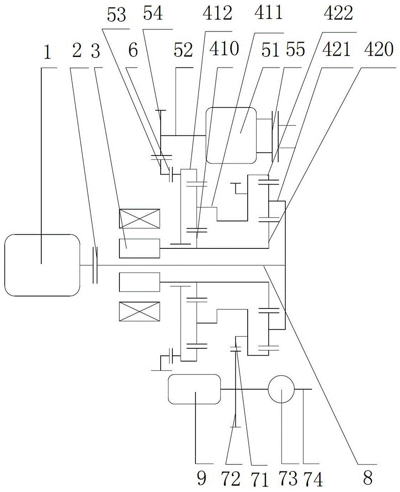
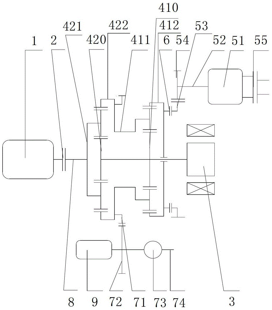
[0027] see figure 1 , The present invention provides an energy storage and drive device that can be applied to hybrid electric vehicles; including an engine 1, a first clutch 2, a first motor / generator 3, a power distribution mechanism, a flywheel module, a second clutch 6 and a power output Device; The power distribution mechanism is a double-row planetary gear transmission.

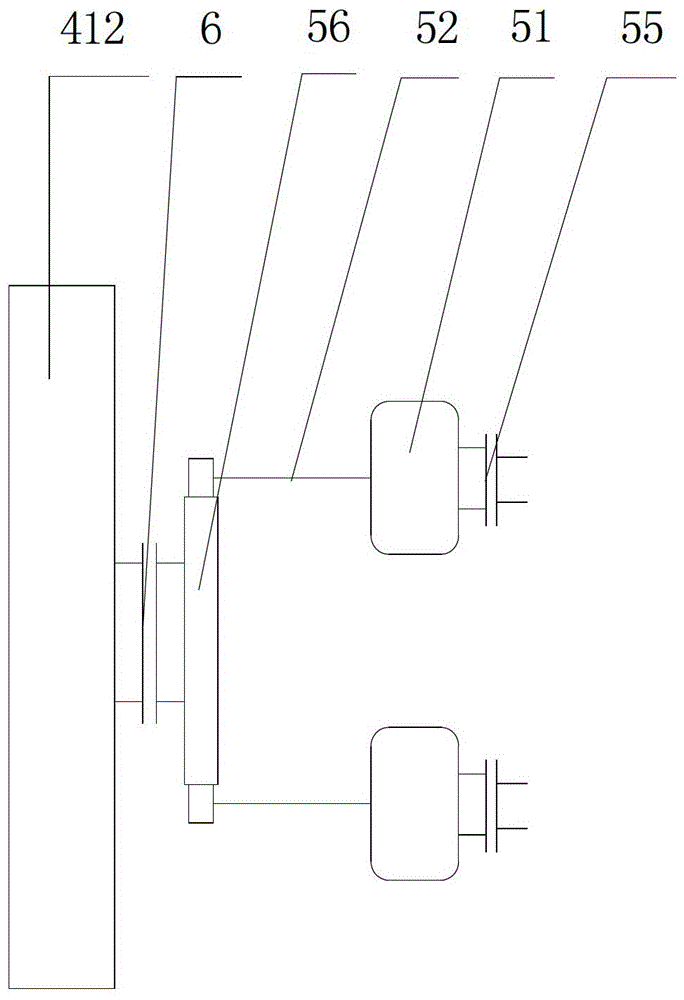
[0028] see image 3 The flywheel module includes a flywheel speed increasing driving gear 53, at least one flywheel speed increasing driven gear 54 meshing with the flywheel speed increasing driving gear 53, at least one flywheel 51, at least one flywheel shaft 52 and at least one flywheel brake 55; the meshing gear pair 56 includes a flywheel speed-increasing driving gear 53 and a flywheel speed-increasing driven gear 54; the power output device includes a reduction driving gear 71, a reduction driven gear 72, a speed change device 73, and a power output shaft 74; The engine 1 and the first clutch 2 are i...


PUM


Abstract

The invention relates to an energy storing and driving device allowed to be applied to a hybrid electric vehicle. The energy storing and driving device comprises an engine, a first clutch, a first motor / generator, a power distribution mechanism, a flywheel module, a second clutch and a power output device, wherein the power distribution mechanism is a double-row planetary gear transmission device; the flywheel module comprises a flywheel speed increasing driving gear, at least one flywheel speed increasing driven gear meshed with the flywheel speed increasing driving gear, at least one flywheel, at least one flywheel shaft and at least one flywheel brake; the power output device comprises a speed reducing driving gear, a speed reducing driven gear, a speed changing device and a power output shaft. The problems that brake energy is low in recovery efficiency and the acceleration performance is poor are solved. The energy storing and driving device has the advantages of high recovery efficiency of the brake energy, excellent acceleration performance, low cost of the finished vehicle and remarkable energy-saving effect.

Description

Technical field [0001] The invention relates to the technical field of hybrid electric vehicles, in particular to an energy storage and driving device applicable to hybrid electric vehicles. Background technique [0002] Mankind is faced with the two major challenges of the gradual exhaustion of fossil energy and the deterioration of the environment caused by excessive dependence on fossil energy. The rapid development of traditional vehicles powered by petroleum energy is causing humans to fall into a dual crisis of resources and the environment. Therefore, the development of energy-saving and environmentally friendly new energy sources Automobiles have gradually become the development trend of the industry. [0003] A hybrid electric vehicle (HEV) is a vehicle driven by an engine and a motor system. It is in line with the mainstream development direction of environmental protection and high efficiency. According to the number of power sources and the power transmission method, it...

Claims


Application Information

Patent Timeline
Patent Type & Authority Patents(China)
IPC IPC(8): B60K6/30B60K6/365
CPCY02T10/62Y02T10/92
Inventor 汪训定水佑民杨敏范绍军
Owner CHANGZHOU HAIKE NEW ENERGY TECH
Why Eureka
Try Eureka