
grinding wheel

A grinding wheel and grinding technology, applied in the direction of abrasives, bonded grinding wheels, metal processing equipment, etc., can solve the problems of not knowing the fastening screw, the grinding wheel is not installed properly, and the fastening bolt is deformed

Active Publication Date: 2018-04-24
DISCO CORP
View PDF5 Cites 0 Cited by
  • Summary
  • Abstract
  • Description
  • Claims
  • Application Information

AI Technical Summary

Problems solved by technology

[0006] However, for example an unskilled operator may not know or forget to tighten the opposing screws serially, but instead, for example in a circumferential sequence, resulting in the grinding wheel not being properly mounted to the grinding device wheel seat
[0007] If the grinding wheel is not properly mounted to the wheel seat, there is a possibility of damage to the spindle due to deformation of the fastening bolts, or the grinding wheel rotates off-center

Method used


Image

  • grinding wheel
  • grinding wheel
  • grinding wheel

Examples


Embodiment Construction

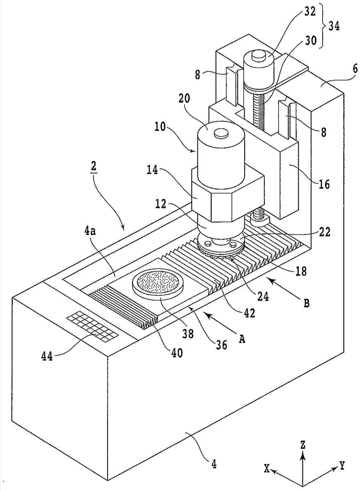
[0027] Hereinafter, embodiments of the present invention will be described in detail with reference to the drawings. refer to figure 1 , shows an external perspective view of a grinding device 2 suitable for installing the grinding wheel of the present invention. Reference numeral 4 denotes a base of the grinding device 2 , and a column 6 is erected behind the base 4 . A pair of guide rails 8 extending in the vertical direction are fixed to the column 6 .

[0028] A grinding unit (grinding member) 10 is installed so as to be movable in the up and down direction along the pair of guide rails 8 . The grinding unit 10 has a spindle housing 12 and a support portion 14 holding the spindle housing 12 , and the support portion 14 is attached to a moving base 16 that moves vertically along the pair of guide rails 8 .

[0029] The grinding unit 10 includes: a main shaft 18 rotatably accommodated in a main shaft housing 12; a motor 20 which drives the main shaft 18 to rotate; a wheel...


PUM


Abstract

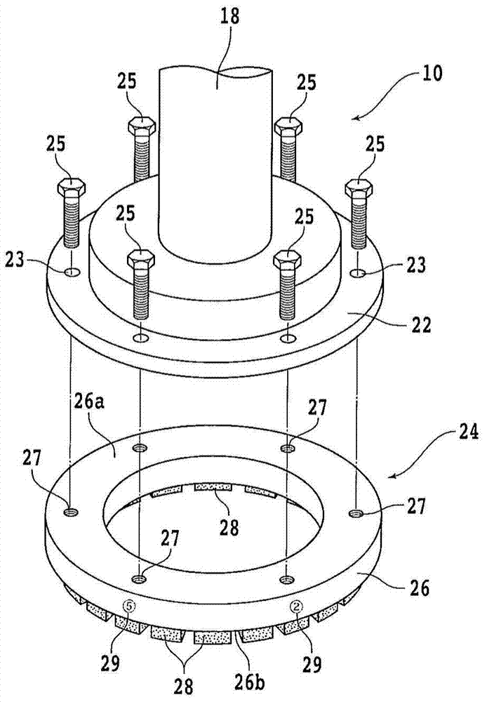
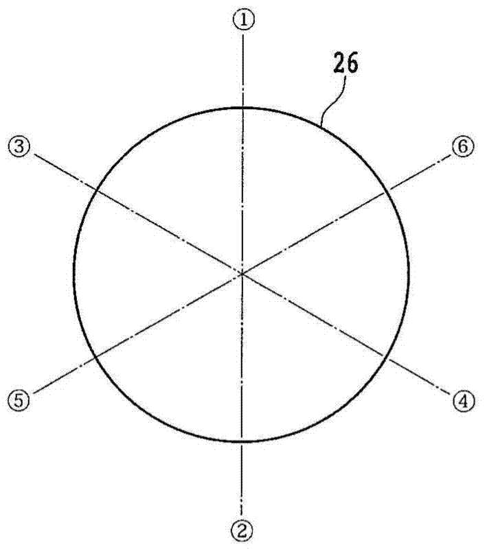
The invention provides a grinding wheel. No matter who the operator is, the grinding wheel can be properly fastened to the wheel base of the grinding device. A grinding wheel, which is detachably mounted on a wheel seat fixed at the end of a main shaft of a grinding device, the grinding wheel is characterized in that the grinding wheel is provided with: an annular wheel base having a The mounting portion and the free end on the opposite side of the mounting portion; and a plurality of grinding tools, which are arranged on the free end of the annular wheel base, and on the mounting portion of the annular wheel base A plurality of internally threaded portions into which fastening bolts are screwed are separately formed in the circumferential direction, and the grinding wheel has fastening sequence display marks indicating the sequence of fastening the internally threaded portions.

Description

technical field [0001] The present invention relates to a grinding wheel detachably attached to a wheel base of a grinding device. Background technique [0002] Multiple devices such as ICs and LSIs are formed on the surface of the semiconductor wafer, and each device is divided by a predetermined dividing line (spacer), and the semiconductor wafer is processed to a specified thickness by grinding the back surface of the semiconductor wafer with a grinding device Afterwards, the semiconductor wafer is divided into individual devices by cutting the dividing line with a dicing device, and the divided devices are widely used in various electronic devices such as mobile phones and personal computers. [0003] A grinding device for grinding the back surface of a wafer is provided with: a chuck table holding a wafer; a grinding tool for grinding the wafer; and a grinding liquid supply member which supplies the grinding liquid to the grinding area, and the grinding device can grin...

Claims


Application Information

Patent Timeline
Patent Type & Authority Patents(China)
IPC IPC(8): B24D7/06
Inventor 胡天令蒋礼
Owner DISCO CORP
Learn More