Methods of Extracting Condensate from Charge Air Coolers

An air cooler and condensate technology, applied in electrical control, exhaust gas recirculation, machine/engine, etc., can solve the problems of increasing component cost and complexity

Inactive Publication Date: 2018-06-01
FORD GLOBAL TECH LLC
View PDF5 Cites 0 Cited by
  • Summary
  • Abstract
  • Description
  • Claims
  • Application Information

AI Technical Summary

Problems solved by technology

While this can reduce condensate levels in the CAC, the condensate moves to an alternate location or storage, which may be affected by other condensation issues such as icing or corrosion
Additionally, memory can add to component cost and complexity

Method used


Image

  • Methods of Extracting Condensate from Charge Air Coolers
  • Methods of Extracting Condensate from Charge Air Coolers
  • Methods of Extracting Condensate from Charge Air Coolers

Examples


Embodiment Construction

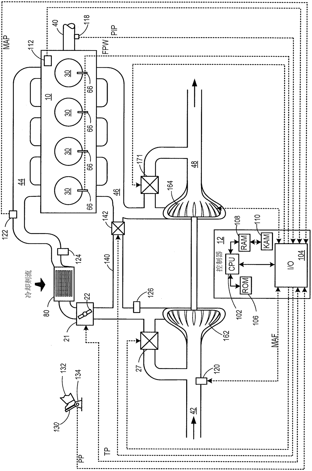
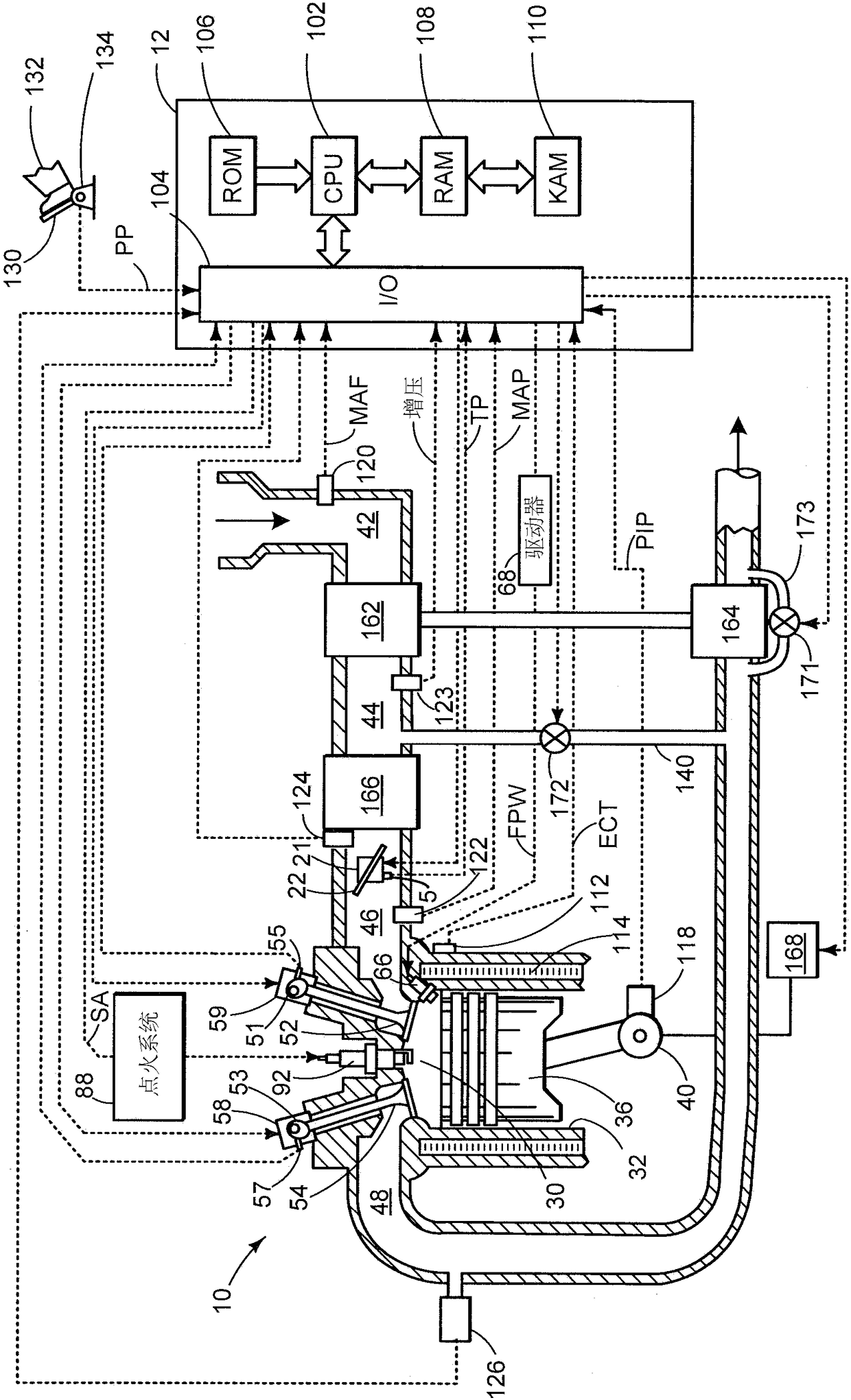
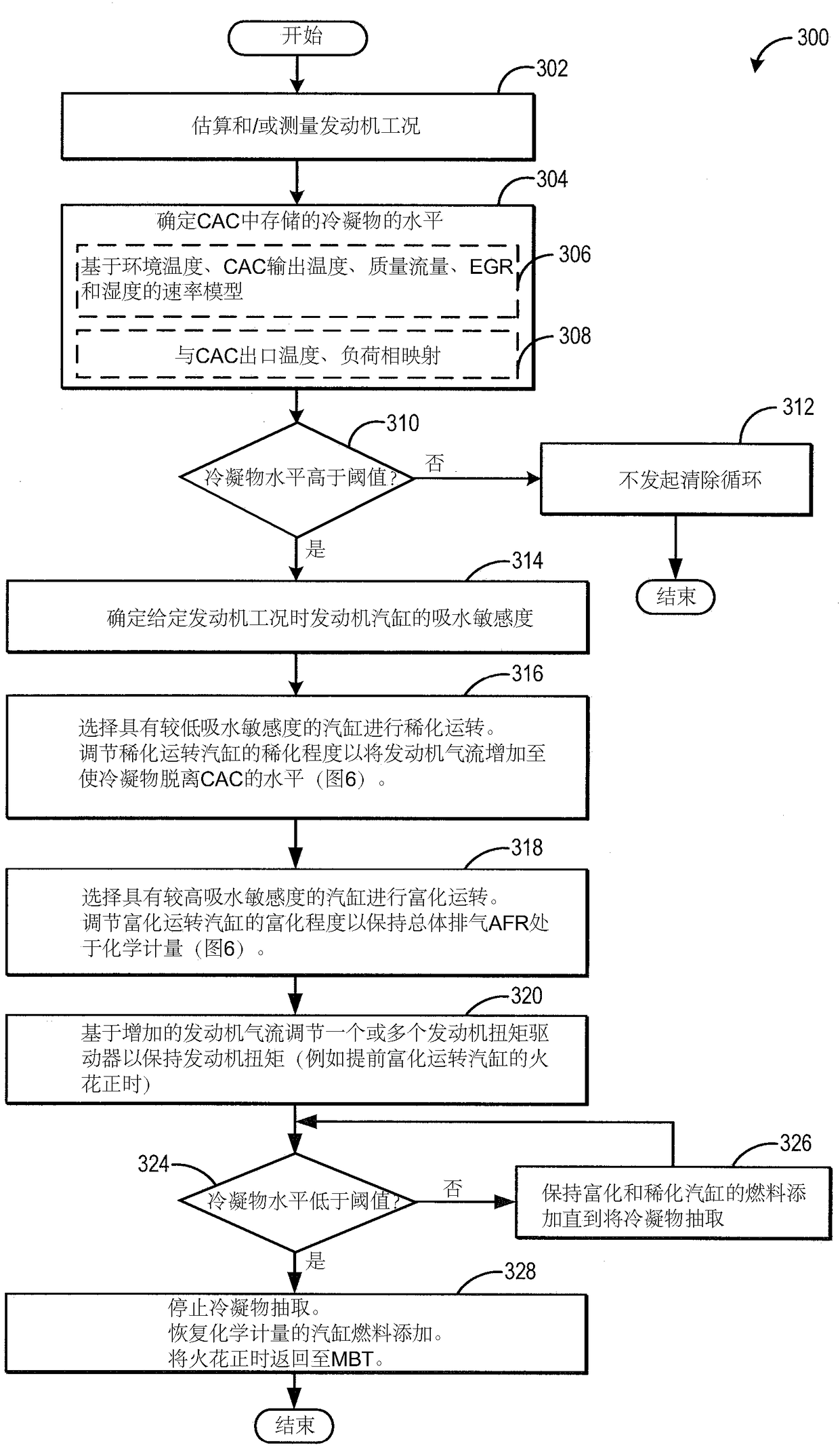
[0029] The following description refers to the extraction of condensate from the charge air cooler (CAC) to engine systems such as Figure 1-2 System and method in the system). During purging, engine airflow may be temporarily increased while engine actuators (such as spark timing) are adjusted in response to condensate flow. CAC condensate purging may occur in response to elevated condensate levels. The engine controller can be configured to execute control programs such as image 3 procedure in ) to adjust per-cylinder fueling during purging based on each cylinder's water absorption sensitivity ( Figure 5 ). Alternatively, the controller can execute Figure 4 The example routine in to adjust fuel injection timing to provide a lean stratified mode of cylinder combustion. The controller can operate one or more cylinders rich and run others lean by adjusting the degree of richness and leanness to maintain exhaust emissions ( Figure 6-8 ). In any event, engine airflow i...


PUM


Abstract

A method and system for removing condensate stored in a charge air cooler is disclosed. In response to increased condensate buildup in the charge air cooler, airflow through the engine is increased to purge the condensate while adjusting engine drive to maintain engine torque. The problem of combustion stability of the engine cylinders is solved by individually adjusting the fueling of each cylinder during the ingestion of condensate.

Description

【Technical field】 [0001] The present invention relates to a method and system for extracting condensate from a charge air cooler without degrading combustion stability. 【Background technique】 [0002] Turbocharged and supercharged engines can be configured to compress ambient air entering the engine to increase power. Compressing air can lead to an increase in air temperature, so a charge air cooler (CAC) can be utilized to cool the hot air, increasing air density and further increasing the potential power of the engine. Ambient air from outside the vehicle flows through the CAC to cool the intake air flowing through the interior of the CAC. Condensate may form in the CAC when the ambient air temperature decreases or during humid or rainy conditions when the intake air is cooled below the dew point of the water. Condensate can collect at the bottom or internal passages of the CAC and at the cooling turbulators. When torque increases (such as during acceleration), the incr...

Claims


Application Information

Patent Timeline
Patent Type & Authority Patents(China)
IPC IPC(8): F02D41/00F02B29/04
CPCF02B29/0425F02B29/0437F02B29/0468F02B29/0475F02D13/0219F02D41/0065F02D41/0085F02D41/1475F02D2041/1472F02M25/0227F02M26/05F02M26/10Y02T10/12Y02T10/40F02D23/00F02D33/006F02D41/0007F02D41/0052F02D41/008F02D41/0295F02D41/042F02D41/045F02D41/047F02D41/3076
Inventor C·P·格鲁格拉K·R·诺曼S·S·山田J·M·金德里C·斯蒂尔
Owner FORD GLOBAL TECH LLC
Why Eureka
Try Eureka