A turbocharger for an exhaust pipe and its installation structure

A technology of eddy current supercharging and installation structure, which is applied in the direction of exhaust device, muffler device, machine/engine, etc. It can solve the problems of reducing gasoline combustion efficiency, output power, gas flow speed, and large airflow resistance, etc., and achieves convenience and speed Effects of installation, faster flow, and improved installation performance

Inactive Publication Date: 2017-11-14
张湘杰 +4
View PDF8 Cites 0 Cited by
  • Summary
  • Abstract
  • Description
  • Claims
  • Application Information

AI Technical Summary

Problems solved by technology

[0003] One of the purposes of the present invention is to solve the problem that the pipeline between the combustion chamber of the existing automobile engine and the muffler is relatively long, so that the air flow resistance is relatively large, and the flow velocity of the gas is reduced, thereby affecting the suction of the combustion chamber in the next power cycle. The volume of the air, thereby reducing the combustion efficiency of gasoline and the output power of the engine, provides an exhaust pipe turbocharger, which is connected in series between the three-way catalytic converter and the muffler, so that the engine exhaust The inertial vortex is formed in the gas process, so as to increase the exhaust speed and exhaust volume, and then increase the intake air volume of the engine combustion chamber in the next work cycle, thereby improving the combustion efficiency of gasoline, increasing the engine output power, and improving the exhaust emission of the engine.

Method used


Image

  • A turbocharger for an exhaust pipe and its installation structure
  • A turbocharger for an exhaust pipe and its installation structure
  • A turbocharger for an exhaust pipe and its installation structure

Examples


specific Embodiment 1

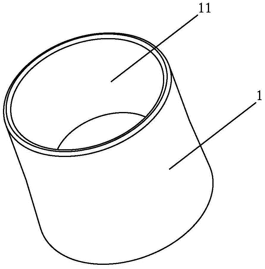
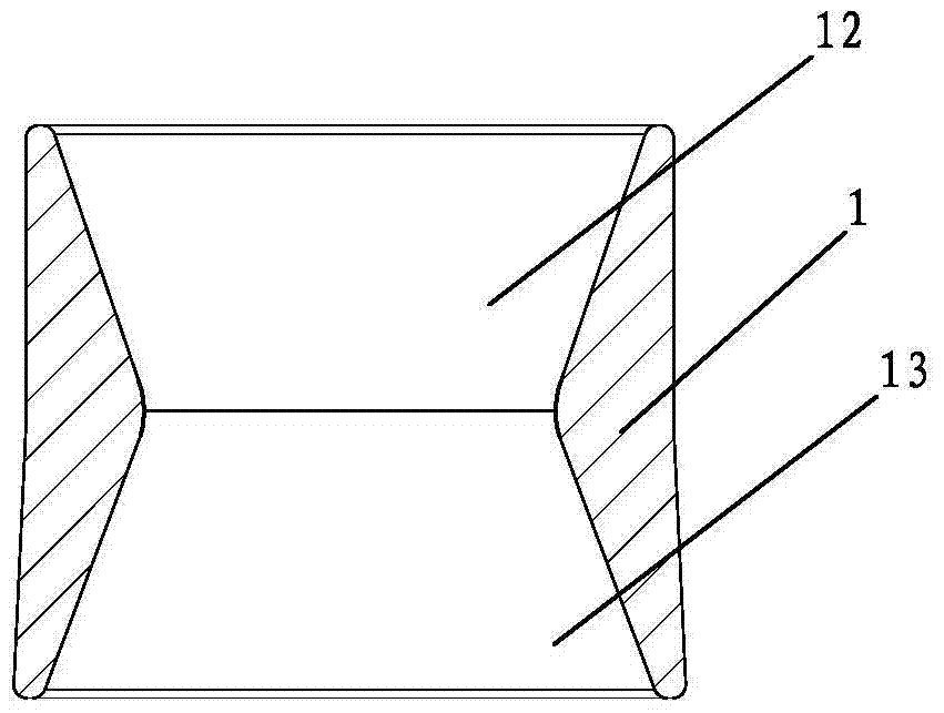
[0028] see figure 1 and figure 2 , the present embodiment relates to an exhaust pipe turbocharger, which is characterized in that it includes a turbocharger body 1, and a through hole 11 is opened on the turbocharger body 1, and the diameter of the through hole 11 is along the The direction of the central axis is distributed from decreasing first and then increasing, and when the gas flows through the through hole 11, a vortex supercharging structure is formed to accelerate the flow velocity of the gas. Specifically, the through hole 11 includes a first tapered hole 12 and a second tapered hole 13 communicating with the first tapered hole 12, and the diameters of the first tapered hole 12 and the second tapered hole 13 are along the The directions of the central axes are gradually distributed from large to small and small to large, respectively. The gas discharged from the combustion chamber flows from the first tapered hole 12 to the second tapered hole 13 or from the seco...

specific Embodiment 2

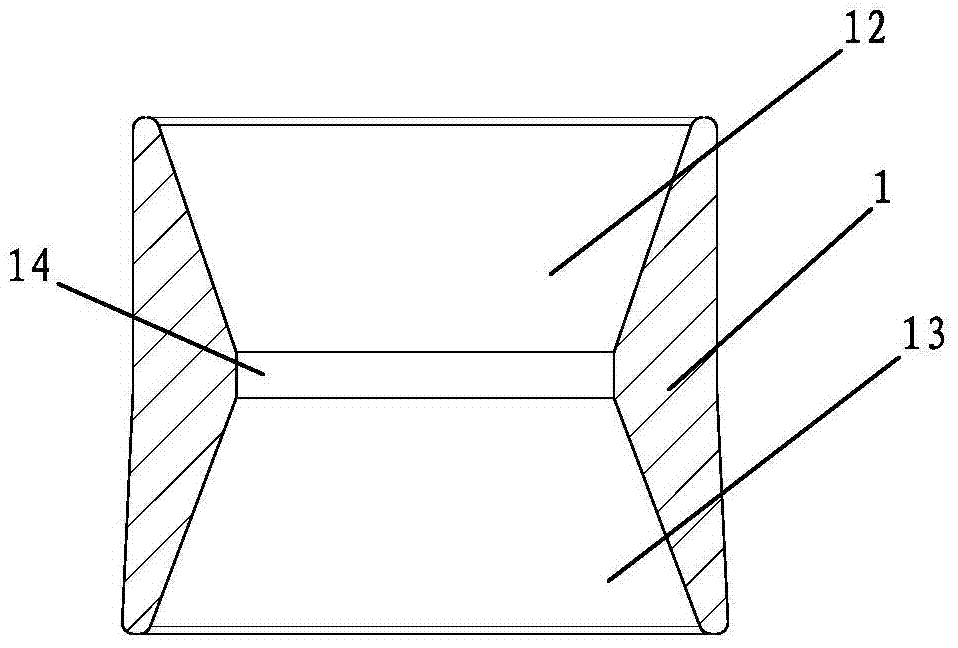
[0034] Such as image 3 As shown, the structure of this embodiment is the same as that of the specific embodiment 1, including a turbocharger body 1, and a through hole 11 is opened on the turbocharger body 1, and the diameter of the through hole 11 is along the direction of its central axis. The direction decreases first and then increases, and when the gas flows through the through hole 11, a vortex supercharging structure is formed to speed up the flow rate of the gas. The difference is: the through hole 11 includes a first tapered hole 12, a straight hole 14 and a second tapered hole 13 connected in sequence, and the diameters of the first tapered hole 12 and the second tapered hole 13 are along the The directions of the central axes are gradually distributed from large to small and small to large, respectively.

specific Embodiment 3

[0035] Such as Figure 4As shown, the structure of this embodiment is the same as that of the specific embodiment 1, including a turbocharger body 1, and a through hole 11 is opened on the turbocharger body 1, and the diameter of the through hole 11 is along the direction of its central axis. The directions are distributed from decreasing first and then increasing, and when the gas flows through the through hole 11, a vortex supercharging structure is formed to speed up the flow velocity of the gas. The difference is: the through hole 11 is a stepped hole, including the first straight hole 111, the second straight hole 112 and the third straight hole 113 connected in sequence, the first straight hole 111 and the third straight hole 113 The diameter is larger than the diameter of the second straight hole 112 .


PUM


Abstract

The invention discloses an exhaust pipe turbo charger. The exhaust pipe turbo charger is characterized by comprising a turbo charger body, through holes are formed in the turbo charger body, the diameters of the through holes are distributed in the direction of the central axes of the through holes in the mode of being decreased first and then increased, a turbo charger structure is formed when air flows through the through holes, and the circulation speed of the air is increased. The invention further discloses an installation structure of the exhaust pipe turbo charger. The installation structure of the exhaust pipe turbo charger is characterized in that a three-way catalytic converter and a silencer are connected in a butting mode through a connecting pipe with flange plates, and the turbo charger body is arranged in the connecting pipe. According to the exhaust pipe turbo charger and the installation structure thereof, an inertial eddy is formed in the process of engine exhaust, therefore, the effect that the exhaust velocity and the exhaust quantity are improves is achieved, then the air inflow of an engine combustor in a next acting period is improved, accordingly, the combustion efficiency of gasoline is improved, the engine output is promoted, and the exhaust gas emission of the engine is improved.

Description

technical field [0001] The invention relates to a vortex supercharger, in particular to a vortex supercharger used for an exhaust pipe and its installation structure. Background technique [0002] During the working process of the car, the gasoline located in the combustion chamber of the engine is ignited, and the high-pressure gas generated by it pushes the piston to do work and discharges the low-pressure gas after the work to the external environment, so that the car can perform work through the work of the high-pressure car. drive. In order to reduce the noise produced by automobile exhaust, an external muffler is used on the exhaust port of the engine on the existing automobile. Then, since the engine is located at the front end of the car and the muffler is located at the rear end of the car, a straight line must be passed through the exhaust port of the engine. The long pipe is connected with the muffler. Although the muffler of this structure has a good noise redu...

Claims


Application Information

Patent Timeline
Patent Type & Authority Patents(China)
IPC IPC(8): F01N13/08F01N13/18
Inventor 张湘杰朱国江白冀海
Owner 张湘杰
Why Eureka
Try Eureka