Device and method for measuring ultrasonic power in a semi-anechoic water tank

A technology of ultrasonic power and measurement method, applied to measurement devices, vibration measurement in fluid, measurement of vibration and other directions, can solve problems such as affecting calibration results, inability to intercept radiated sound waves, and inability to confirm the distance between the transmitter and the reflective target, and achieve calibration. Accurate and reliable results

Active Publication Date: 2017-02-22
THE 715TH RES INST OF CHINA SHIPBUILDING IND CORP
View PDF6 Cites 1 Cited by
  • Summary
  • Abstract
  • Description
  • Claims
  • Application Information

AI Technical Summary

Problems solved by technology

In the preparation stage, the initial state of the target can only be observed and adjusted from the upper part of the water tank; in the full coverage state, the distance between the transmitter and the reflector target cannot be confirmed, and if it is too close, the reflected wave will directly return to the surface of the transmitter, while the working distance If it is too far away, the reflective target may not be able to intercept most of the radiated sound waves, which will affect the calibration results, so it is generally necessary to change multiple distance measurement data to ensure the accuracy of the results

Method used


Image

  • Device and method for measuring ultrasonic power in a semi-anechoic water tank
  • Device and method for measuring ultrasonic power in a semi-anechoic water tank
  • Device and method for measuring ultrasonic power in a semi-anechoic water tank

Examples


Embodiment Construction

[0026] Below in conjunction with accompanying drawing and embodiment the present invention will be further described:

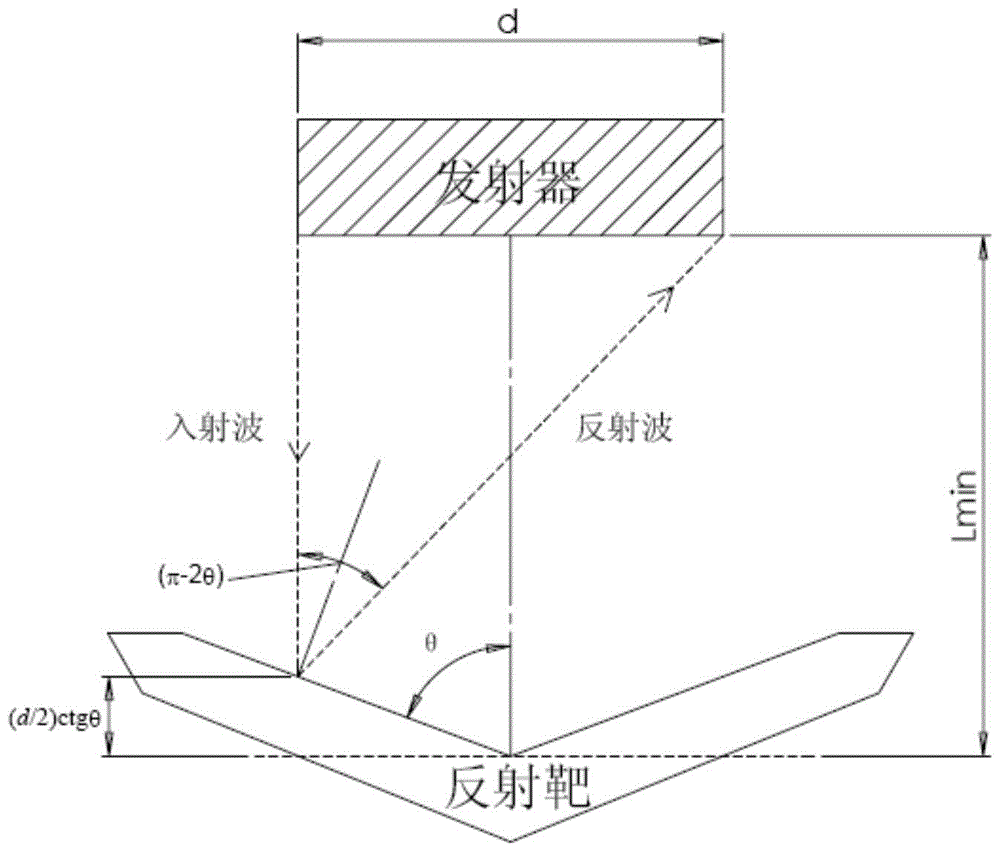
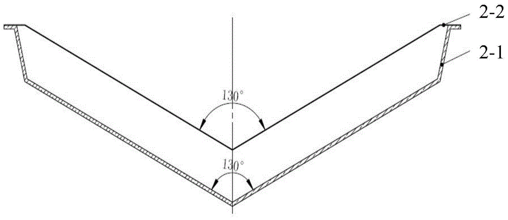
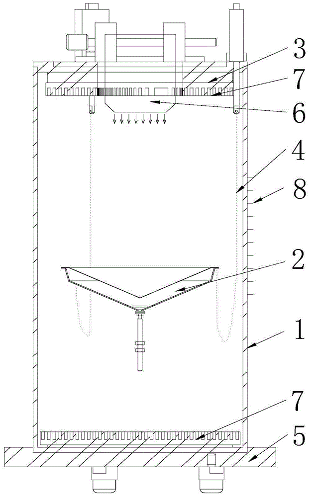
[0027] Such as Figure 1-3 As shown, the device for measuring ultrasonic power in this semi-anechoic water tank realizes the measurement of ultrasonic radiation sound power. The upper and lower inner surfaces are pasted with sufficient sound-absorbing materials, and the cylindrical water tank with smooth, transparent and untreated side walls uses reflection targets Ultrasonic power measurement in this water tank has the remarkable characteristics of being able to confirm the initial state of the target in all directions, observe the measurement process in real time, and improve measurement effectiveness and work efficiency. It mainly includes a semi-sound-absorbing water tank 1 and electronic instruments. The semi-sound-absorbing water tank 1 includes a transparent round tube with a scale line 8, an upper cover 3 and a lower cover 5. No sound-absorbing materi...


PUM


Abstract

The invention relates to a device and method for measuring ultrasonic power in a half-noise-elimination water tank. The device mainly comprises the half-noise-elimination water tank and an electronic instrument. The half-noise-elimination water tank comprises a transparent circular tube with scale lines, an upper cover plate and a lower cover plate. A reflection target is fixed through a thin chain located on the upper cover plate and then is suspended in the half-noise-elimination water tank. An ultrasonic transmitter is fixed to the water surface in the middle of the upper cover plate. The radiating surface of the ultrasonic transmitter is immersed under water. The ultrasonic transmitter transmits sound waves downwards from the upper portion of the half-noise-elimination water tank. A sound absorption material layer is pasted to the lower cover plate used for sealing the bottom of the transparent circular tube. The sound absorption material layer absorbs the sound waves transmitted into the lower cover plate. The device and method have the advantages that the reflection target is used for ultrasonic power measurement in the water tank, and reflected waves can be prevented from influencing a measurement result on the condition of a certain distance, so that the measuring process is clear and discernible; when the device and method are used for ultrasonic power measurement, the outstanding advantages that the site state is grasped at any time, anomaly is analyzed, and the effectiveness and the working efficiency of measurement are improved are achieved.

Description

technical field [0001] The invention relates to the field of ultrasonic power measurement, more precisely, it relates to a device and method for measuring ultrasonic power in a semi-anechoic water tank. Background technique [0002] Acoustic power is one of the main technical indicators in the design of transmitting transducers and arrays. Commonly used calibration methods include sound pressure method, sound intensity method and near-field method. For the calibration of the sound power of several hundred kHz underwater acoustic transmitters, as the frequency increases, the wavelength becomes shorter, the directivity becomes sharper, and the far-field measurement distance is longer. Higher requirements have been put forward, and the commonly used calibration methods are not suitable. [0003] The Ultrasound Technical Committee of the International Electrotechnical Commission recommends the radiation pressure method as a method for ultrasonic power measurement in liquids in ...

Claims


Application Information

Patent Timeline
Patent Type & Authority Patents(China)
IPC IPC(8): G01H3/10
Inventor 黄勇军王世全朱学文
Owner THE 715TH RES INST OF CHINA SHIPBUILDING IND CORP
Why Eureka
Try Eureka