
A circuit and method for fast acquisition of dynamic parameters of power electronic devices

A technology of power electronic devices and dynamic parameters, which is applied in the direction of instruments, measuring electricity, measuring electrical variables, etc., can solve the problems that it is difficult to compare dynamic parameters with voltage and current changes, etc.

Active Publication Date: 2017-10-10
NORTH CHINA ELECTRIC POWER UNIV (BAODING) +2
View PDF8 Cites 0 Cited by
  • Summary
  • Abstract
  • Description
  • Claims
  • Application Information

AI Technical Summary

Problems solved by technology

For the dynamic characteristics of the device, the double pulse method is used in traditional research and national standards to measure, but each double pulse experiment can only obtain one turn-on and turn-off process, and it is the whole turn-on and turn-off process under the condition of one voltage and one current. This requires a lot of repeated experiments to obtain the parameters of power electronic devices under different voltage and different current conditions.
In addition, the double-pulse method is not easy to compare the relationship between dynamic parameters and voltage and current changes.

Method used


Image

  • A circuit and method for fast acquisition of dynamic parameters of power electronic devices
  • A circuit and method for fast acquisition of dynamic parameters of power electronic devices

Examples


Embodiment Construction

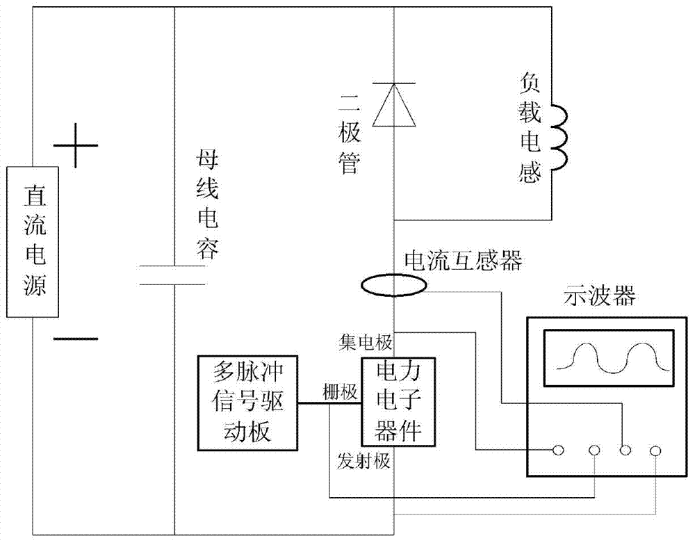
[0018] The preferred embodiments will be described in detail below in conjunction with the accompanying drawings. Such as figure 1 As shown, DC power supply, bus capacitor, multi-pulse signal driver board, diodes, power electronic devices, load inductance, current transformer, and oscilloscope. The power electronic device in this embodiment takes IGBT as an example, according to figure 1 After building the circuit in the schematic diagram of the circuit, select the DC power supply, voltage measurement probe, and current transformer according to the test voltage and current level.

[0019] Then determine the period and number of multi-pulse signals. The low-level time of the multi-pulse signal should not be too short. Too short will cause the tail current of the device to be unable to reproduce during the turn-off phase; the low-level time of the multi-pulse signal should not be too long. Too long will cause the load inductor current A large drop occurs during shutdown. The...


PUM


Abstract

The invention belongs to the field of power electronic device measuring techniques and particularly relates to a circuit and method for quickly obtaining dynamic parameters of a power electronic device. The circuit mainly comprises a direct-current power supply, a bus capacitor, a multi-pulse signal driver board, a diode, the power electronic device, a load inductor, a current transformer and an oscilloscope. The method is mainly used for changing dipulse testing in national standards into multi-pulse testing with pulse widths, high-low level duration and the number of pulses adjustable. By measuring voltage, currents and multi-pulse signal waveforms of the two ends of the power electronic device, multiple turn-on and turn-off process waveforms and the dynamic parameters under different currents are obtained at a time, and human adjustment can be carried out according to simulated testing currents.

Description

technical field [0001] The invention belongs to the technical field of power electronic device measurement, and in particular relates to a circuit and method for quickly acquiring dynamic parameters of a power electronic device. Background technique [0002] With the development of direct current transmission and power electronic technology, the application of power electronic devices is becoming more and more extensive. With the increase of switching frequency, the research on the dynamic characteristics of power electronic devices is becoming more and more important. For the dynamic characteristics of the device, the double pulse method is used in traditional research and national standards to measure, but each double pulse experiment can only obtain one turn-on and turn-off process, and it is the whole turn-on and turn-off process under the condition of one voltage and one current. This requires a lot of repeated experiments to obtain the parameters of power electronic d...

Claims


Application Information

Patent Timeline
Patent Type & Authority Patents(China)
IPC IPC(8): G01R31/00
Inventor 齐磊邹凯凯崔翔赵国亮鲍伟蔡林海
Owner NORTH CHINA ELECTRIC POWER UNIV (BAODING)
Learn More