Smelting furnace capable of automatically ascending and descending

An automatic lifting and melting furnace technology, which is applied in the direction of furnaces, crucible furnaces, furnace components, etc., can solve problems affecting the normal operation of melting furnaces, increase work difficulty, increase difficulty, etc., and achieve labor saving, simple design and low cost.

Active Publication Date: 2015-02-11
SANMENXIA HENGHE ELECTRICAL TECH
View PDF5 Cites 0 Cited by
  • Summary
  • Abstract
  • Description
  • Claims
  • Application Information

AI Technical Summary

Problems solved by technology

[0002] Traditional smelting furnaces are relatively simple in structure, usually only equipped with a heating chamber. When the smelting product needs to be poured out after smelting, the smelting furnace must be tilted, and during the pouring process, part of the smelting liquid will adhere to the On the outer wall of the melting furnace, it not only causes waste, but also affects the normal operation of the melting furnace, and also brings a lot of inconvenience to the staff. In addition, the crucible is lifted out, which increases the difficulty of the work, and the crucible will be accidentally dropped. Top flip, increasing the difficulty for the staff

Method used


Image

  • Smelting furnace capable of automatically ascending and descending
  • Smelting furnace capable of automatically ascending and descending
  • Smelting furnace capable of automatically ascending and descending

Examples


Embodiment 1

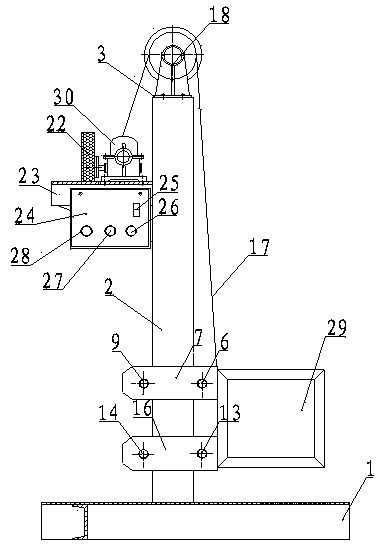
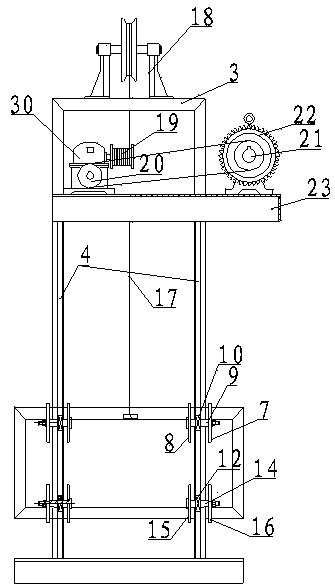
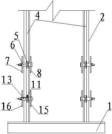
[0017] Such as Figure 1-3 Shown: an automatic lifting smelting furnace, which includes a base 1, two columns 2 are installed on the left end of the base 1, and a horizontal frame 3 is connected between the tops of the two columns 2, and the two columns The front and rear sides of the column 2 are respectively provided with grooved tracks 4, and the two columns 2 are respectively equipped with a sliding system with a symmetrical structure. The sliding system includes a bearing A5, and the bearing A5 is interspersed with Axis A6, the two ends of the axis A6 are respectively connected to the limiting plate A7 and the limiting plate B8, the limiting plate A7 and the limiting plate B8 are symmetrically installed on the outer sides of the left and right sides of the column 2, so The bearing A5 described above is arranged in the groove track 4 on the front side of the column and the shaft A6 is respectively connected to the front ends of the limiting plate A7 and the limiting plate ...

Embodiment 2

[0020] Such as Figure 1-3 Shown: an automatic lifting smelting furnace, which includes a base 1, two columns 2 are installed on the left end of the base 1, and a horizontal frame 3 is connected between the tops of the two columns 2, and the two columns The front and rear sides of the column 2 are respectively provided with grooved tracks 4, and the two columns 2 are equipped with a sliding system with a symmetrical structure. The sliding system includes a bearing A5, and the bearing A5 is interspersed with Axis A6, the two ends of the axis A6 are respectively connected to the limiting plate A7 and the limiting plate B8, the limiting plate A7 and the limiting plate B8 are symmetrically installed on the outer sides of the left and right sides of the column 2, so The bearing A5 described above is arranged in the groove track 4 on the front side of the column and the shaft A6 is respectively connected to the front ends of the limiting plate A7 and the limiting plate B8, and the r...


PUM


Abstract

The invention relates to a smelting furnace capable of automatically ascending and descending. The smelting furnace comprises a base, wherein two stand columns are mounted on the base and connected with a cross frame, groove tracks are formed in the stand columns, a sliding system is mounted on the stand columns and comprises a bearing A, a shaft A penetrates through the bearing A, two ends of the shaft A are connected with a limit plate A and a limit plate B, one shaft B penetrates through rear ends of the limit plate A and the limit plate B, a bearing B is mounted on shaft B, the limit plate A and the limit plate B are connected with a furnace body, a bearing C and a bearing D are arranged between the bearing A and the bearing B, a shaft C and a shaft D are mounted on the bearing C and the bearing D and connected with a limit plate C and a limit plate D, the front ends of the limit plate C and the limit plate D are connected with the furnace body which is connected with a steel wire rope, the steel wire rope is connected with a pulley, the pulley is connected with a winding reel which is connected with a gearbox, the gearbox is connected with a pinion, the pinion is connected with a big gear wheel which is connected with a motor, the winding reel, the pinion, the motor and the big gear wheel are connected with a support frame, and the support frame is provided with a control switch panel. The smelting furnace is convenient to use.

Description

technical field [0001] The invention belongs to the field of smelting design, in particular to a melting furnace, in particular to an automatic lifting melting furnace. Background technique [0002] Traditional smelting furnaces are relatively simple in structure, and usually only have a heating chamber. When the smelting product needs to be poured out after smelting, the smelting furnace must be tilted, and during the pouring process, part of the smelting liquid will adhere to On the outer wall of the melting furnace, it not only causes waste, but also affects the normal operation of the melting furnace, and also brings a lot of inconvenience to the staff. In addition, the crucible is lifted out, which increases the difficulty of the work, and the crucible will be accidentally dropped. The top flip increases the difficulty for the staff. Contents of the invention [0003] The object of the present invention is to overcome the deficiencies of the prior art and provide a s...

Claims


Application Information

Patent Timeline
Patent Type & Authority Applications(China)
IPC IPC(8): F27B14/08F27D1/00
Inventor 楚克超李长松董治发马兴灿
Owner SANMENXIA HENGHE ELECTRICAL TECH
Why Eureka
Try Eureka