
Cover for electronic device, antenna assembly, electronic device, and method for manufacturing the same

A technology for electronic devices and antenna assemblies, applied in antenna parts, antennas, antenna coupling and other directions, can solve the problems of uninstructed changing eddy currents, undisclosed metal covers, etc.

Inactive Publication Date: 2015-02-25
SAMSUNG ELECTRO MECHANICS CO LTD
View PDF7 Cites 39 Cited by
  • Summary
  • Abstract
  • Description
  • Claims
  • Application Information

AI Technical Summary

Problems solved by technology

However, this document does not disclose the technical concept of using a metal cover without a physical slit as an antenna, nor does it teach the technical concept of changing the path of the eddy current without forming a physical slit in the metal cover

Method used


Image

  • Cover for electronic device, antenna assembly, electronic device, and method for manufacturing the same
  • Cover for electronic device, antenna assembly, electronic device, and method for manufacturing the same
  • Cover for electronic device, antenna assembly, electronic device, and method for manufacturing the same

Examples


Embodiment Construction

[0056] Hereinafter, exemplary embodiments will be described in detail with reference to the accompanying drawings in this disclosure.

[0057] This disclosure, however, may be illustrated in many different ways and should not be construed as limited to the specific embodiments set forth herein. Rather, these embodiments are provided so that this disclosure will be thorough and complete, and will fully convey the scope of the disclosure to those skilled in the art.

[0058] In the drawings, the shapes and dimensions of components may be exaggerated for clarity, and the same reference numerals will be used throughout to designate the same or like components.

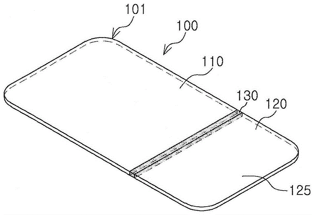
[0059] figure 1 is a perspective view illustrating a cover for an electronic device according to an exemplary embodiment in the present disclosure.

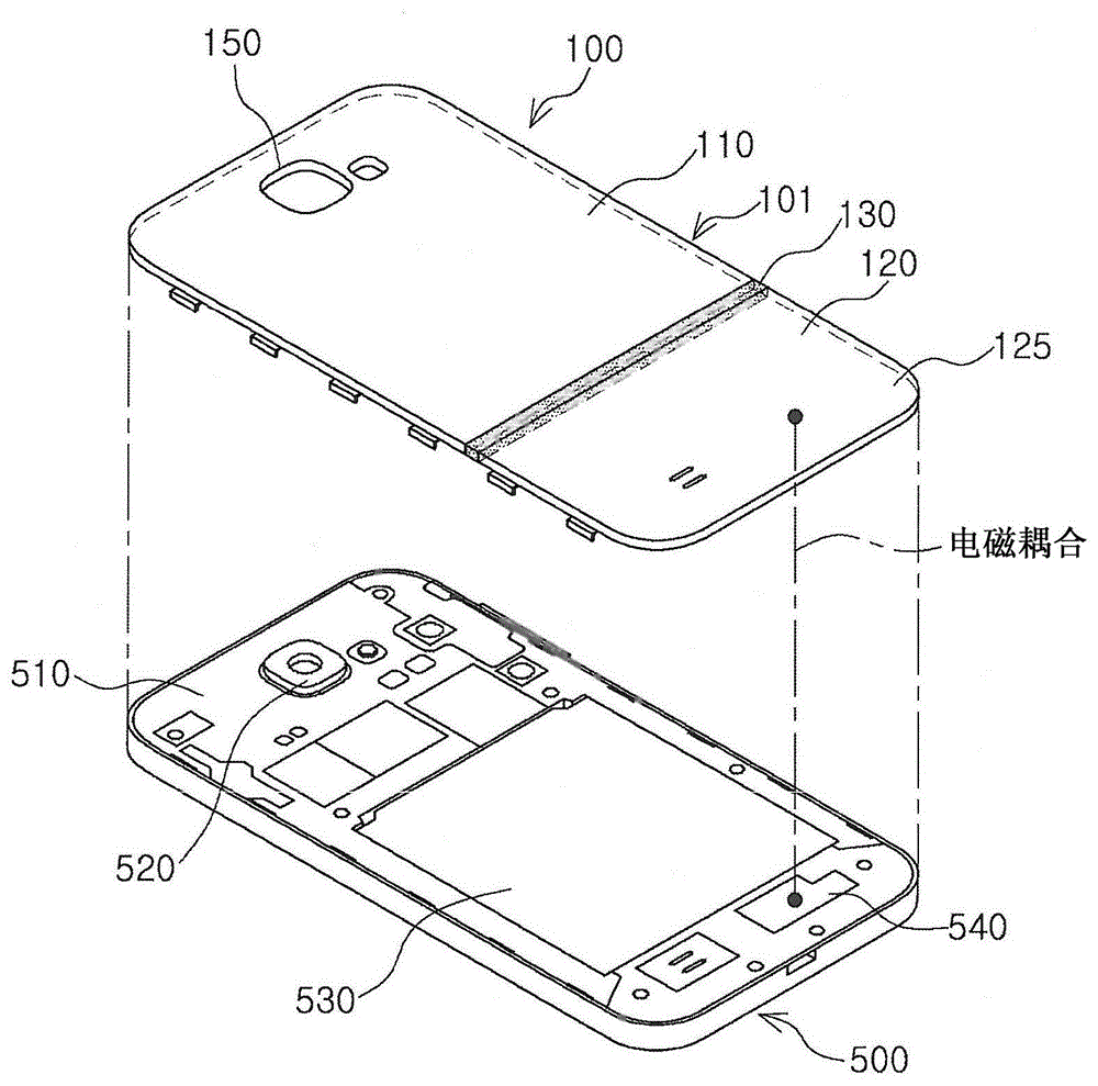
[0060] refer to figure 1 , the cover 100 for an electronic device according to an exemplary embodiment of the present disclosure may include a metal plate 101 , an electri...


PUM


Abstract

A cover (100) for an electronic device may include a metal plate (101) having a first metal region (110) formed of a metal; a through-hole (150) formed in a portion of the first metal region (110) of the metal plate (101); and an electrical open path (180) extending from the through-hole (150) to an end portion on one side of the first metal region (110) through metal oxidation. The cover of the electronic device can be used as an antenna and the oxidation process electrically separates the metal plate such that eddy currents are reduced and the antenna recognition distance is increased.

Description

[0001] Cross References to Related Applications [0002] This application claims the benefit of Korean Patent Application No. 10-2013-0096933 filed in the Korean Intellectual Property Office on Aug. 14, 2013 and No. 10-2014-0011684 filed on Jan. 29, 2014, incorporated by reference Its entire content is incorporated herein. technical field [0003] The present disclosure relates to a cover for an electronic device, an antenna assembly, an electronic device, and a method of manufacturing the same. Background technique [0004] Generally, antennas can be classified into external antennas installed outside the electronic device and built-in antennas installed inside the electronic device. There is increasing interest in built-in antennas to provide various advantages in terms of ease of use, design, and more. [0005] With the advancement of communication technology, portable terminals such as cellular phones have become multifunctional in order to provide voice calling, text ...

Claims


Application Information

Patent Timeline
IPC IPC(8): H01Q1/22H01Q1/38H01Q1/52H01Q7/04
CPCC25D11/022C25D5/48H01Q1/243C25D11/04H01Q7/04H01Q9/40C25D11/30C25D5/022C25D7/00H04M1/0202C25D11/26H04M1/0249
Inventor 全大成金钟来崔刚龙
Owner SAMSUNG ELECTRO MECHANICS CO LTD
Learn More