Squeezing mechanism for oil press

An oil press and press rod technology, applied in the direction of presses, manufacturing tools, etc., can solve the problems of affecting the oil output efficiency of the press mechanism, troublesome operation of the press mechanism, and inability of the machine to discharge slag, etc., to ensure the quality and efficiency of the press. Smooth and easy-to-operate effect

Active Publication Date: 2015-03-04
河北宏润油脂工业有限公司
View PDF9 Cites 8 Cited by
  • Summary
  • Abstract
  • Description
  • Claims
  • Application Information

AI Technical Summary

Problems solved by technology

The disadvantage of this type of structure is: the operation of the pressing mechanism of this type of structure is cumbersome, and the user needs to replace and connect the slag discharge sleeve according to different oil materials, and when the slag discharge sleeve is connected to the press chamber, since the user performs the connection operation, the tightening force varies depending on the weight. There is a difference, it is impossible to make the slag discharge sleeve in the best position to cooperate with the press chamber, which also affects the oil discharge efficiency of the press mechanism
In addition, in order to increase the oil output efficiency, it is mandatory to use a small slag discharge sleeve for large particle materials. The machine cannot discharge slag, and the machine may not work or directly cause the motor to burn out, which may damage the machine.

Method used


Image

  • Squeezing mechanism for oil press
  • Squeezing mechanism for oil press
  • Squeezing mechanism for oil press

Examples


Embodiment 1

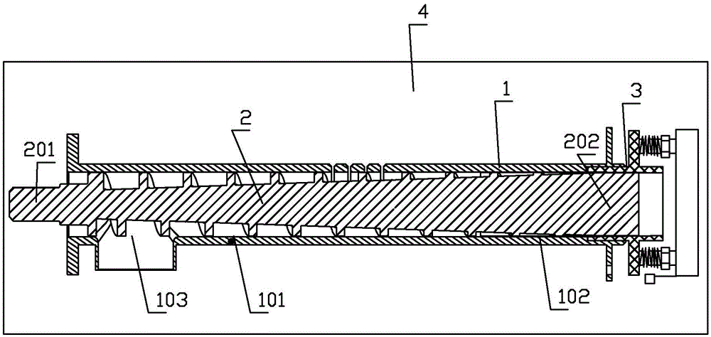
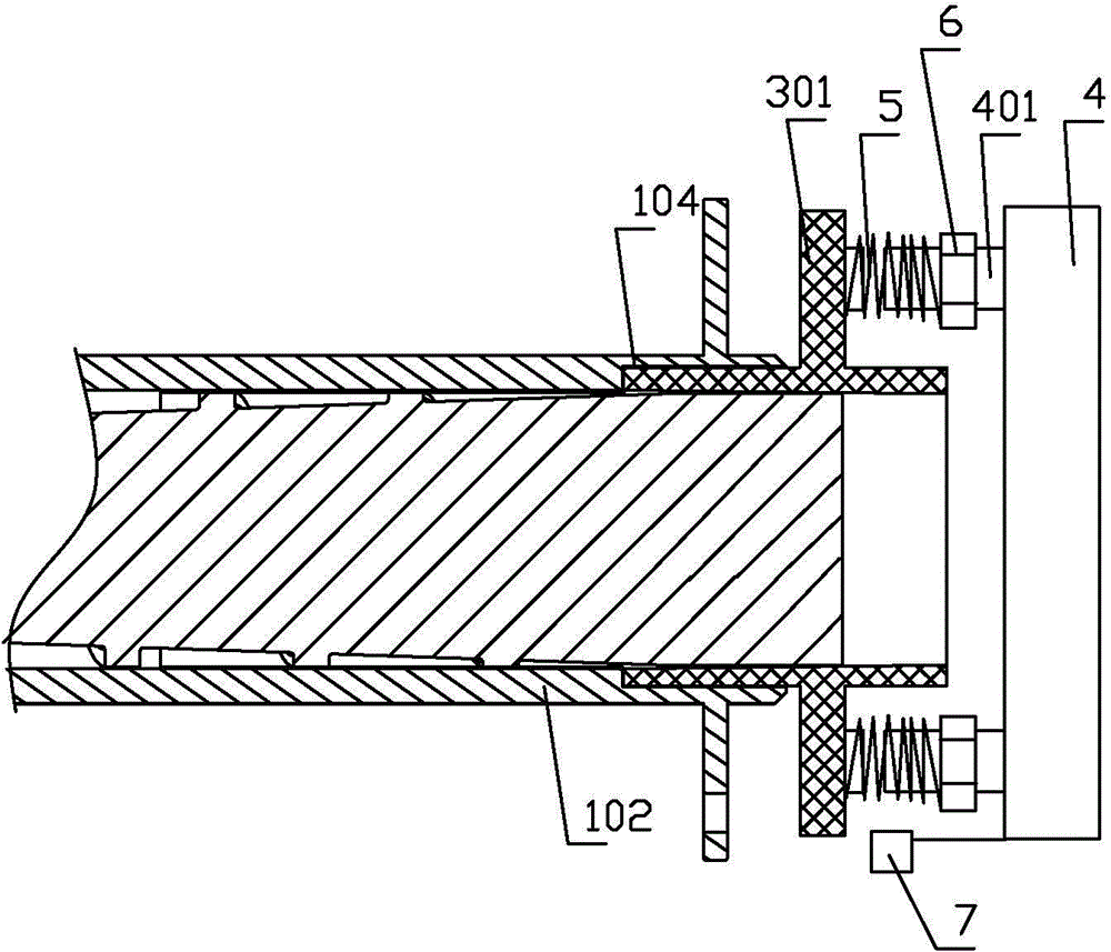
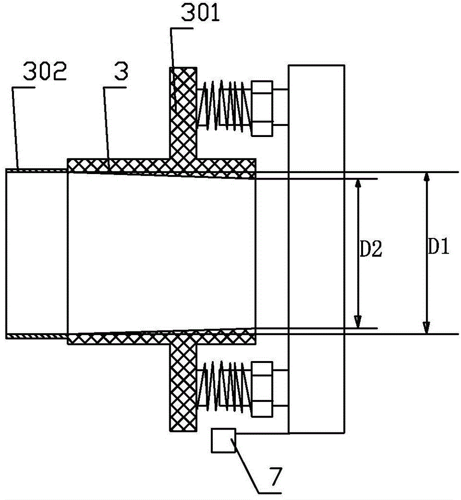
[0025] Embodiment 1: as Figure 1 to Figure 4 As shown, a pressing mechanism of an oil press includes a frame, a pressing chamber 1, and a pressing rod 2, and the pressing rod 2 is located in the pressing chamber 1; the pressing chamber includes a conveying material section 101 and a squeezing section 102; There is a feeding hole 103, the conveying section and the pressing section are arranged in sequence, the conveying section and the pressing section are integrally formed, and the conveying section and the pressing section are on the same axis; the inner wall of the end of the pressing section 102 is provided with an outwardly recessed ring The sliding groove 104; the sliding groove 104 is provided with a cylindrical part 3 that can slide in the horizontal direction, and the outer wall of the cylindrical part 3 matches the sliding groove.

[0026] The pressing chamber 1 is fixed on the frame 4, and the part of the cylindrical part 3 located outside the pressing chamber is pr...


PUM


Abstract

The invention discloses a squeezing mechanism for an oil press. A part of a cylinder part positioned outside a barrel is provided with a stress part; a horizontal adjusting column is arranged on a frame corresponding to the stress part; a spring is arranged on the adjusting column; one end of the spring is pressed against the stress part; the other end of the spring is pressed against an adjusting nut which is in threaded connection with the adjusting column; the aperture of the inner wall of the inner end of the cylinder part is greater than the aperture of the inner wall of the outer end of the cylinder part; the aperture of the part of inner wall between the inner end of the cylinder part and the outer end of the cylinder part is reduced gradually; an outward extending part is arranged at the inner end of the cylinder part; the extending part extends into a squeezing segment; the outer wall of the extending part is matched with the inner wall of the squeezing segment. Dynamic balance to the working situation is realized through the movement of the cylinder part, and the problem of failure in working of the squeezing mechanism or even damage to a motor due to poor oil discharge efficiency occurring in an oil squeezing process and forced increase of the oil discharge efficiency is solved. The squeezing mechanism has high oil discharge efficiency and high squeezing efficiency, and does not damage any machine.

Description

technical field [0001] The invention relates to a squeezing mechanism of a household oil press, which can be used for squeezing large and small oil plants such as peanuts and sesame. Background technique [0002] In the prior art, the general squeezing mechanism is composed of a squeeze rod and a squeeze chamber, and the rear end of the squeeze chamber is detachably connected with a slag discharge cover; There is a slag discharge groove on the inner wall, and the size of the through hole matches the end of the squeeze rod to support the end of the squeeze rod; three slag discharge grooves are evenly distributed in the through hole. When the same slag discharge sleeve is used, if the slag discharge tank is of a large size, it may be just right (that is, to maintain a considerable pressing speed and oil yield) when pressing peanut oil, but when pressing sesame (small particle) oil, due to The small oil seeds have small particles, and these small oil plants may come out of the...

Claims


Application Information

Patent Timeline
Patent Type & Authority Applications(China)
IPC IPC(8): B30B9/14B30B15/00
Inventor 古博文
Owner 河北宏润油脂工业有限公司
Why Eureka
Try Eureka