Oil expression system with controllable oil expression assembly

A technology of components and pressing rods, applied in the direction of presses, manufacturing tools, etc., can solve the problems of affecting the oil output efficiency of the pressing mechanism, troublesome operation of the pressing mechanism, and difficult to clean the pressing rods and pressing chambers, so as to achieve compact structure, easy processing, Good work stability

Inactive Publication Date: 2016-10-26
陈妙娟
View PDF0 Cites 0 Cited by
  • Summary
  • Abstract
  • Description
  • Claims
  • Application Information

AI Technical Summary

Problems solved by technology

The disadvantage of this type of structure is: the operation of the pressing mechanism of this type of structure is cumbersome, and the user needs to replace and connect the slag discharge sleeve according to different oil materials, and when the slag discharge sleeve is connected to the press chamber, since the user performs the connection operation, the tightening force varies depending on the weight. There is a difference, it is impossible to make the slag discharge sleeve in the best position to cooperate with the press chamber, which also affects the oil discharge efficiency of the press mechanism
In addition, in order to increase the oil output efficiency, it is mandatory to use a small slag discharge sleeve for large particle materials. The machine cannot discharge slag, and the machine may not work or directly cause the motor to burn out, which may damage the machine.
[0003] In addition, during the cleaning process of oil pressing and pressing chamber, the material residue will stick to the pressing rod (especially in the thread groove), making it difficult to clean the pressing rod and pressing chamber
Generally, the press rod and the press chamber are separated for cleaning, which is troublesome to operate.

Method used


Image

  • Oil expression system with controllable oil expression assembly
  • Oil expression system with controllable oil expression assembly
  • Oil expression system with controllable oil expression assembly

Examples


Embodiment 1

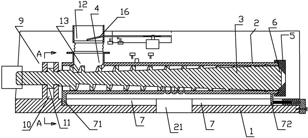
[0057] Embodiment 1: as Figure 1 to Figure 15 As shown, an oil extraction system with a controllable oil extraction component includes a frame 200, a feeding device 201 (feed box), a transmission mechanism 300, and an electric controllable oil extraction component are arranged on the frame 200. The oil press mainly includes a frame 200, a feeding device 201 (feed box), a transmission mechanism 300, and an electric controllable oil pressing assembly are arranged on the frame 200.

[0058] The transmission mechanism 300 includes a motor 301 and a bevel gear set, and the transmission shaft of the motor is connected to the bevel gear set.

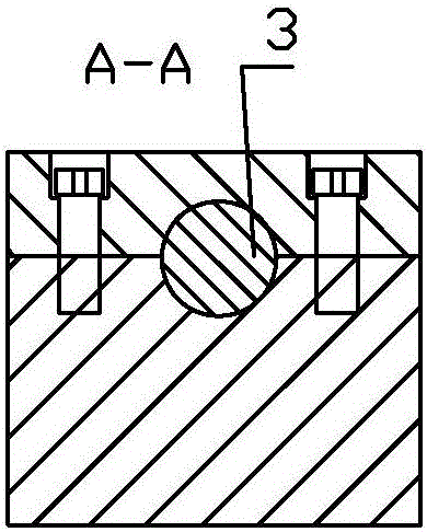
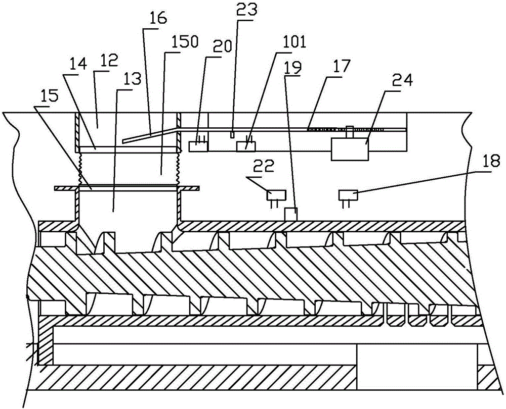
[0059] The electric controllable oil pressing assembly includes a component seat 1, a pressing chamber 2, and a pressing rod 3. The pressing rod 3 is located in the pressing chamber; the pressing chamber 2 includes a conveying material section and a pressing section; The conveying section and the pressing section are arranged in sequence, the...


PUM


Abstract

The invention discloses an oil pressing system with a controllable oil pressing assembly, which comprises a frame, a feeding device, a transmission mechanism, and an electrically controllable oil pressing assembly are arranged on the frame; a feeding control plate is inserted into the upper feeding barrel , the outer end of the material control plate is hinged with one end of the toothed bar, and the toothed bar meshes with the motor M that can rotate in both directions; there is a touch piece on the press chamber, and a normally open switch K1 is set on the right side of the touch piece; the left side of the touch piece There is a normally open switch K3 on the side; the normally open switch K1 is electrically connected to the input terminal of the relay KM; the actions of the normally open switch KM1, the normally open switch KM2 and the normally open switch KM3 are controlled by the relay KM. The present invention realizes the dynamic balance and adapts to different working conditions by using the movement of the press chamber and the adjustment of the material control plate. The press rod and the press chamber are combined together. Compared with the prior art bulk type press rod and press chamber, the structure is well coordinated, the working stability is good, and the oil output capacity is strong. It can be cleaned without detaching the press rod and press chamber independently.

Description

technical field [0001] The invention relates to a household oil pressing system with a controllable oil pressing assembly. The pressing mechanism can be used for pressing peanuts, beans, sesame and other large and small oil plants. Background technique [0002] In the prior art, the general press mechanism is composed of a press rod and a press chamber, and the rear end of the press chamber is detachably connected with a slag discharge sleeve; in order to solve the problem of oil production efficiency and slag discharge of different oil species, the press chamber can Select different slagging sleeves, for example, when pressing oil with large particles of peanuts, use the slagging sleeve with a large slagging tank; For granular oil, the oil will come out of the slag discharge tank without deep pressing, and it will not affect the pressing efficiency of the pressing mechanism. The disadvantage of this type of structure is: the operation of the pressing mechanism of this type...

Claims


Application Information

Patent Timeline
Patent Type & Authority Applications(China)
IPC IPC(8): B30B15/00B30B9/14
CPCB30B15/00B30B9/14
Inventor 傅强
Owner 陈妙娟
Why Eureka
Try Eureka