Movable type oil press mechanism

A movable type and pressing rod technology, which is applied in the direction of presses, manufacturing tools, etc., can solve the problems of affecting the oil output efficiency of the pressing mechanism, troublesome operation of the pressing mechanism, and inability to discharge slag from the machine, so as to achieve small gaps, easy processing, and high pressing efficiency high effect

Inactive Publication Date: 2016-08-31
陈妙娟
View PDF6 Cites 0 Cited by
  • Summary
  • Abstract
  • Description
  • Claims
  • Application Information

AI Technical Summary

Problems solved by technology

The disadvantage of this type of structure is: the operation of the pressing mechanism of this type of structure is cumbersome, and the user needs to replace and connect the slag discharge sleeve according to different oil materials, and when the slag discharge sleeve is connected to the press chamber, since the user performs the connection operation, the tightening force varies depending on the weight. There is a difference, it is impossible to make the slag discharge sleeve in the best position to cooperate with the press chamber, which also affects the oil discharge efficiency of the press mechanism
In addition, in order to increase the oil output efficiency, it is mandatory to use a small slag discharge sleeve for large particle materials. The machine cannot discharge slag, and the machine may not work or directly cause the motor to burn out, which may damage the machine.

Method used


Image

  • Movable type oil press mechanism
  • Movable type oil press mechanism
  • Movable type oil press mechanism

Examples


Embodiment 1

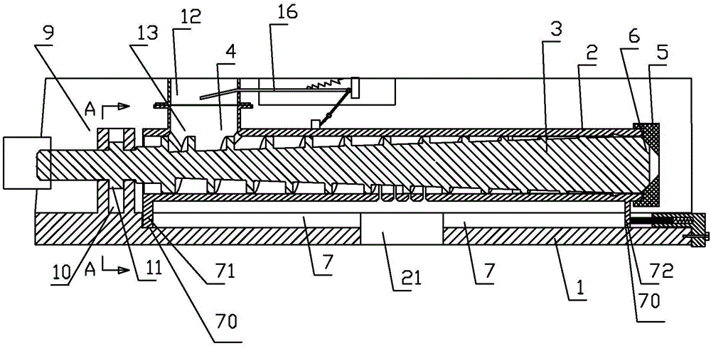
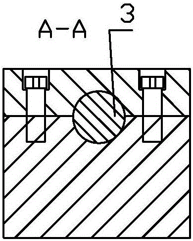
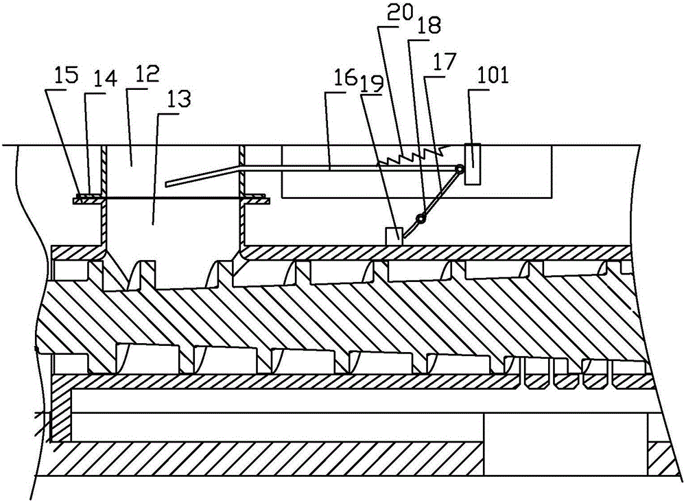
[0024] Embodiment 1: as Figure 1 to Figure 6 As shown, a movable oil press mechanism includes a component seat 1, a press chamber 2, and a press rod 3, and the press rod 3 is located in the press chamber; the press chamber 2 includes a conveying section and a pressing section; the conveying section is provided with a feeding Hole 4, the conveying section and the pressing section are arranged in sequence, the conveying section and the pressing section are integrally formed, and the conveying section and the pressing section are on the same axis; the end of the pressing section is detachably connected with a tail sleeve 5; The end is provided with a platform body section 6 , the outer diameter of the platform body section 6 gradually becomes smaller in the axially outward direction, and the inner wall of the tail sleeve 5 matches the outer wall 60 of the platform body section 6 .

[0025] The component seat 1 is provided with a sliding groove 7, and the squeeze chamber 3 is pro...


PUM


Abstract

The invention discloses a movable type oil press mechanism; an upper feed barrel and a lower feed barrel are arranged above a feeding port; the bottom of the lower feed barrel is jointed with the feeding port; the bottom of the upper feed barrel makes contact with the top of the lower feed barrel; the end face of the lower end of the upper feed barrel radially extends outwards to form an extension portion; the end face of the top end of the lower feed barrel radially extends outwards to form an extension portion; the upper feed barrel is used for connecting with a feed device; the upper and lower feed barrels can mutually move; the upper feed barrel is plugged with a material control board; the outer end of the material control board is hinged to one end of a rotary bar; the rotary bar can rotate around a rotary pin; a press barrel is provided with a trigger piece; the trigger piece is arranged corresponding to the other end of the rotary bar; the movable type oil press mechanism also comprises a tension spring used for resetting the material control board. The press barrel and the material control board can be regulated to realize dynamic balance, thus adapting to different work conditions; the material control board can be automatically regulated in a movable process of the press barrel, thus suiting oil seeds of different sizes.

Description

technical field [0001] The invention relates to a household movable oil pressing mechanism, which can be used for pressing peanuts, beans, sesame and other large and small oil plants. Background technique [0002] In the prior art, the general press mechanism is composed of a press rod and a press chamber, and the rear end of the press chamber is detachably connected with a slag discharge sleeve; in order to solve the problem of oil production efficiency and slag discharge of different oil species, the press chamber can Select different slagging sleeves, for example, when pressing oil with large particles of peanuts, use the slagging sleeve with a large slagging tank; For granular oil, the oil will come out of the slag discharge tank without deep pressing, and it will not affect the pressing efficiency of the pressing mechanism. The disadvantage of this type of structure is: the operation of the pressing mechanism of this type of structure is cumbersome, and the user needs ...

Claims


Application Information

Patent Timeline
IPC IPC(8): B30B9/14B30B15/00B30B15/30B30B15/28
CPCB30B9/14B30B15/00B30B15/288B30B15/30
Inventor 傅强
Owner 陈妙娟
Why Eureka
Try Eureka