Swing self-reset bridge bent frame with ductility replaceable collar beam and installation method thereof

An installation method and self-reset technology, applied in the direction of erecting/assembling bridges, bridges, bridge parts, etc., can solve the problems of unresolved seismic strength and stability of bent frame systems, heavy impact on urban traffic and environment, and speeding up construction progress. Achieve the effect of reducing adverse effects, reducing concrete cracking damage, and speeding up construction progress

Inactive Publication Date: 2015-03-25
DALIAN MARITIME UNIVERSITY
View PDF5 Cites 16 Cited by
  • Summary
  • Abstract
  • Description
  • Claims
  • Application Information

AI Technical Summary

Problems solved by technology

[0003] The existing large-scale bridge bents are realized by the traditional cast-in-place method, which has a long construction period and has a heavy impact on urban traffic and the environment;
[0004] Factory prefabrication of pier columns, cap beams, main beams and other main force-bearing components, and on-site assembly into a prefabricated-assembled bridge can greatly speed up the construction progress and reduce the impact on urban traffic and environmental problems, which is very promising. However, the seismic strength and stability of the whole bent system of this bridge has been an unresolved problem.

Method used


Image

  • Swing self-reset bridge bent frame with ductility replaceable collar beam and installation method thereof
  • Swing self-reset bridge bent frame with ductility replaceable collar beam and installation method thereof
  • Swing self-reset bridge bent frame with ductility replaceable collar beam and installation method thereof

Examples


Embodiment Construction

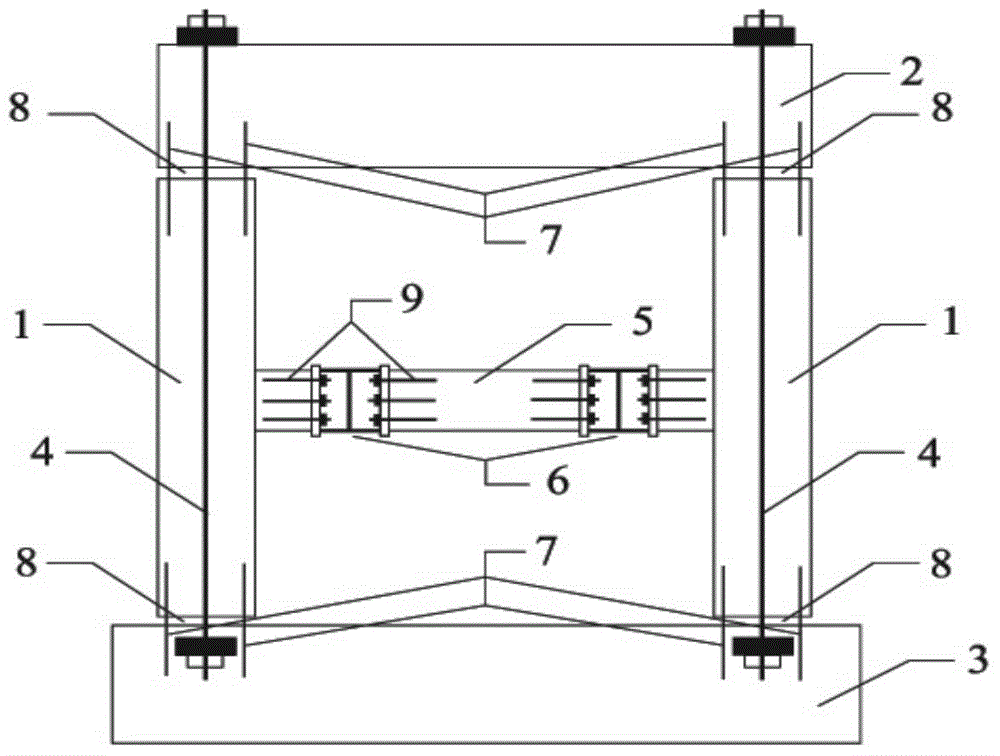
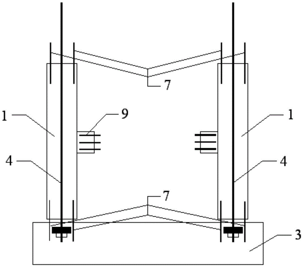
[0033] Such as figure 1 The swinging self-resetting bridge bent with ductile replaceable tie girders shown includes: bridge foundation 3, prefabricated cover girder 2 and two prefabricated piers 1 set on the bridge foundation 3 for supporting the left and right sides of prefabricated cover girder 2 ; Also includes, a replaceable tie beam 5 arranged laterally between two prefabricated bridge piers 1;

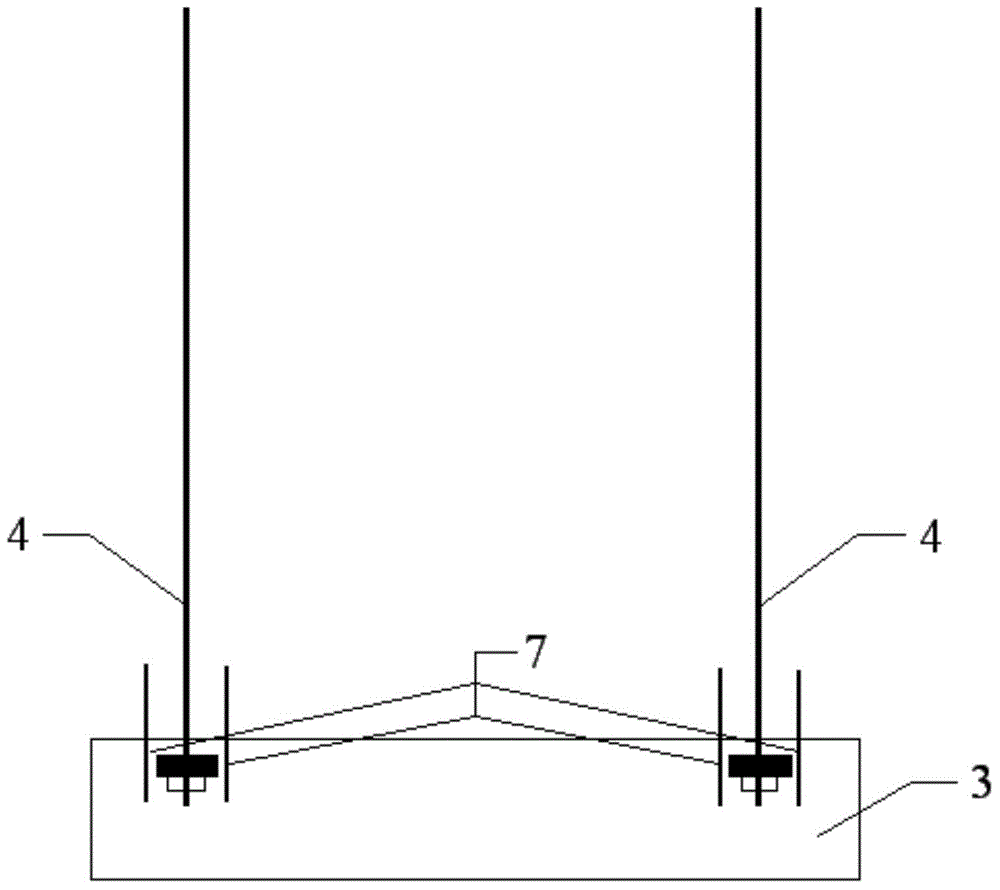
[0034] The prefabricated pier 1 is longitudinally provided with unbonded prestressed tendons 4, and the two ends of the unbonded prestressed tendons 4 protrude from the upper and lower ends of the prefabricated pier 1, and are respectively fixed to the prefabricated cap beam 2 and the bridge foundation 3;

[0035] The joint position of prefabricated bridge pier 1 and prefabricated cover beam 2 is connected by shear key 8; the joint position of prefabricated bridge pier 1 and prefabricated cover beam 2 is also provided with energy-dissipating longitudinal reinforcements fixed to p...


PUM


Abstract

The invention discloses a swing self-reset bridge bent frame with a ductility replaceable collar beam. The swing self-reset bridge bent frame with the ductility replaceable collar beam comprises a bridge foundation, a prefabricated cover beam and two prefabricated piers, wherein the prefabricated piers are arranged on the bridge foundation and used for supporting the left side and the right side of the prefabricated cover beam. The swing self-reset bridge bent frame with the ductility replaceable collar beam further comprises the replaceable collar beam transversely arranged between the two prefabricated piers. Unbonded prestress tendons are longitudinally arranged in the prefabricated piers. The two ends of each unbonded prestress tendon extend out of the upper end and the lower end of the corresponding prefabricated pier and are fixedly connected with the prefabricated cover beam and the bridge foundation respectively. The junction between each prefabricated pier and the prefabricated cover beam is provided with a shear key for connection, and is also provided with an energy dissipation longitudinal bar fixedly connected with the prefabricated pier and the prefabricated cover beam respectively. By the adoption of the technical scheme, the prefabricated parts are assembled rapidly, the overall structure is stable by means of the junctions, the replaceable collar beam and the unbonded prestress tendons, and the swing self-reset bridge bent frame has the swing and self-reset structural characteristic.

Description

technical field [0001] The invention relates to a novel bridge structure system, in particular to a swing self-resetting novel bridge bent structure system. Background technique [0002] The problem of urban traffic congestion is becoming more and more serious, and the only way to solve urban traffic problems is to speed up the construction of urban viaducts and give full play to their three-dimensional traffic advantages; [0003] The existing large-scale bridge bents are realized by the traditional cast-in-place method, which has a long construction period and has a heavy impact on urban traffic and the environment; [0004] Factory prefabrication of pier columns, cap beams, main beams and other main force-bearing components, and on-site assembly into a prefabricated-assembled bridge can greatly speed up the construction progress and reduce the impact on urban traffic and environmental problems, which is very promising. However, the seismic strength and stability of the w...

Claims


Application Information

Patent Timeline
Patent Type & Authority Applications(China)
IPC IPC(8): E01D1/00E01D21/00
CPCE01D1/00E01D19/00E01D19/02E01D21/00
Inventor 孙治国王东升华承俊石岩
Owner DALIAN MARITIME UNIVERSITY
Why Eureka
Try Eureka